Eaton : EASY-E4-AC-16RE1
197222 EASY-E4-AC-16RE1
EASY-E4-AC-16RE1 /Y7-197222
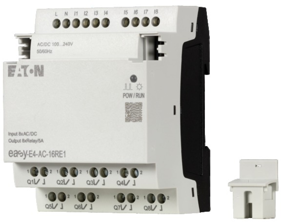
G/Ç genişletme, easyE4 ile kullanım için, 100 - 240 V AC, 110 - 220 V DC (cULus: 100-110 V DC), Giriş genişletme (sayı) dijital: 8, vidalı terminal G/Ç genişletme, Besleme gerilimi: 100 - 240 V AC, 110 - 220 V DC. cULus uygulamalarında tüm V DC Bilgilerine 100-110 VDC uygulanır. easyConnect aracılığıyla kullanılabilir, Montaj konumu: Dikey veya yatay, Koruma tipi (IEC/EN 60529, EN50178, VBG 4): IP20, Standartlar: EN 61000-6-2, EN 61000-6-3, IEC 60068-2- 6, IEC 60068-2-27, IEC 60068-2-30, IEC 60664, IEC 61131-2, EN 61010, EN 50178, UL 61010'a göre cULus, CSA C22.2 No.61010
G/Ç genişletme, easyE4 ile kullanım için, 100 - 240 V AC, 110 - 220 V DC (cULus: 100-110 V DC), Giriş genişletme (sayı) dijital: 8, vidalı terminal
G/Ç genişletme, Besleme gerilimi: 100 - 240 V AC, 110 - 220 V DC. cULus uygulamalarında tüm V DC Bilgilerine 100-110 VDC uygulanır. easyConnect aracılığıyla kullanılabilir, Montaj konumu: Dikey veya yatay, Koruma tipi (IEC/EN 60529, EN50178, VBG 4): IP20, Standartlar: EN 61000-6-2, EN 61000-6-3, IEC 60068-2- 6, IEC 60068-2-27, IEC 60068-2-30, IEC 60664, IEC 61131-2, EN 61010, EN 50178, UL 61010'a göre cULus, CSA C22.2 No.61010
| Product range | Control relays easyE4 |
| Subrange | easyE4 digital input/output enhancements |
| Basic function | easyE4 extensions |
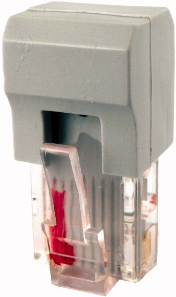
| Description | Input/output extension for easyE4 control relay Expandable with the easyE4 series of digital input/output expansions with easy-E4-CONNECT1 connector (Item Y7-197225) Rated operating voltage 100 to 240 VAC or 100 to 240 VDC (cULus: 100 to 110 VDC) Digital inputs: 8 Digital outputs: 8 relays Screw terminals |
| Inputs expansion (number) | |
| Display | digital: 8 |
| Software | |
| Supply voltage | with diagnostic LED |
| For use with | EASYSOFT-SWLIC/easySoft 7 |
| Standards | 100 - 240 V AC, 100 - 240 V DC (cULus: 100 - 110 V DC) |
| Approvals >Approvals |
easyE4 |
| Approvals >certificate |
|
| Approvals >shipping classification |
EN 61000-6-2 EN 61000-6-3 IEC 60068-2-6 IEC 60068-2-27 IEC 60068-2-30 IEC 61131-2 EN 61010 EN 50178 |
| Approvals | cULus |
| Dimensions (W x H x D) | CE |
| Weight | DNV GL |
| Mounting | |
| Connection type | 71.5 x 90 x 58 mm |
| Screw terminals >Solid |
0.232 kg |
| Screw terminals >flexible |
Top-hat rail IEC/EN 60715, 35 mm or screw fixing using fixing brackets ZB4-101-GF1 (accessories) |
| Screw terminals >Solid or flexible conductor, with ferrule |
screw terminal |
| Screw terminals >Solid or stranded |
|
| Screw terminals >Standard screwdriver |
0.2 - 4 mm2 |
| Screw terminals >Tightening torque |
0.2 - 2.5 mm2 |
| Screw terminals >Stripping length |
0,2 - 2,5 mm2 |
| Operating ambient temperature | 22 - 12 AWG |
| Condensation | 0.8 x 3.5 mm |
| Storage [ϑ] | 0.5 - 0.7 Nm |
| relative humidity | 6.5 mm |
| Air pressure (operation) | |
| Protection type (IEC/EN 60529, EN50178, VBG 4) | -25 to 55, cold as per IEC 60068-2-1, heat as per IEC 60068-2-2 °C |
| Vibrations | Take appropriate measures to prevent condensation |
| Mechanical shock resistance (IEC/EN 60068-2-27) semi-sinusoidal 15 g/11 ms | -40 - +70 °C |
| Drop to IEC/EN 60068-2-31 [Drop height] | in accordance with IEC 60068-2-30, IEC 60068-2-78 5 - 95 % |
| Free fall, packaged (IEC/EN 60068-2-32) | 795 - 1080 hPa |
| Mounting position | |
| Overvoltage category/pollution degree | IP20 |
| Electrostatic discharge (ESD) >applied standard |
In accordance with IEC 60068-2-6 constant amplitude 0.15 mm: 10 - 57 constant acceleration 2 g: 57 - 150 Hz |
| Electrostatic discharge (ESD) >Air discharge |
18 Impacts |
| Electrostatic discharge (ESD) >Contact discharge |
50 mm |
| Electromagnetic fields (RFI) to IEC EN 61000-4-3 | 0.3 m |
| Radio interference suppression | Vertical or horizontal |
| Burst | |
| power pulses (Surge) | III/2 |
| Immunity to line-conducted interference to (IEC/EN 61000-4-6) | according to IEC EN 61000-4-2 |
| Clearance in air and creepage distances | 8 kV |
| Insulation resistance | 6 kV |
| Rated operational voltage [Ue] | 0.8 - 1.0 GHz: 10 1.4 - 2 GHz: 3 2.0 - 2.7 GHz: 1 V/m |
| Permissible range [Ue] | EN 61000-6-3 Class B |
| Residual ripple | according to IEC/EN 61000-4-4 Supply cables: 2 Signal cables: 2 kV |
| Protection against polarity reversal | according to IEC/EN 61000-4-5 1 kV (supply cables, symmetrical) 2 kV (supply cables, asymmetrical) |
| Frequency | 10 V |
| Voltage dips | |
| Fuse | nach EN 50178, EN 61010-2-201, UL61010-2-201, CSA-C22.2 NO. 61010-2-201 |
| Power loss [P] | in accordance with EN 50178, EN 61010-2-201, UL61010-2-201, CSA-C22.2 NO. 61010-2-201 |
| Number | |
| Potential isolation | 100 - 240V DC (-15/+10%) 100 - 240 DC (cULus: 100 -110 DC) (-15/+10%) V |
| Rated operational voltage [Ue] | 85 - 264 V AC 85 - 264 V DC (cULus: 85 - 120 V DC) |
| Input voltage [Ue] | ≦ 5 % |
| Rated frequency | yes |
| Input current at signal 1 | 50/60 (± 5%) Hz |
| Deceleration time | ≤ 20 ms at 100V AC 10 ms at 100V DC ms |
| Cable length | ≧ 1A (T) A |
| Number | Normally 11 W |
| Outputs in groups of | |
| Parallel switching of outputs for increased output | 8 |
| Protection of an output relay | from power supply: no between inputs: no from the outputs: yes to the base unit: yes to the expansion units: yes |
| Potential isolation | 100 - 240 V AC 100 - 240 V DC (cULus: 100 - 110 V DC) V |
| Contacts >Conventional thermal current (10 A UL) |
Condition 0: 0 - 40V AC/DC Condition 1: 79–264 V AC/DC (cULus: 79–264 V AC/79–120 V DC) V |
| Contacts >Recommended for load: 12 V AC/DC |
50/60 Hz |
| Contacts >Rated impulse withstand voltage Uimp of contact coil |
I1 - I8: 8 x 0.25 (at 115V AC, 60 Hz) I1 - I8: 8 x 0.5 (at 230V AC, 50 Hz) I1 - I8: 8 x 0.25 (at 115V DC) I1 - I8: 8 x 0.5 (at 230V DC) mA |
| Contacts >Rated operational voltage [Ue] |
type 39⁄32 (0 - > 1/1 -> 0, 50/60Hz) in AC type 0.5 (0 - > 1/1 -> 0) in DC ms |
| Rated insulation voltage [Ui] | 40 (unshielded) m |
| Safe isolation according to EN 50178 | |
| Making capacity >AC–-15, 250 V AC, 3 A (600 ops./h) [Operations] |
8 |
| Making capacity >DC-13, L/R ≦ 150 ms, 24 V DC, 1 A (500 S/h) [Operations] |
1 |
| Breaking capacity >AC-15, 250 V AC, 3 A (600 Ops./h) [Operations] |
Not permitted |
| Breaking capacity >DC-13, L/R ≦ 150 ms, 24 V DC, 1 A (500 S/h) [Operations] |
B16 circuit breaker or 8 A (T) fuse |
| Filament bulb load >1000 W at 230/240 V AC [Operations] |
Safe isolation according to EN 50178: 300 V AC Basic isolation: 600 V AC from power supply: yes From the inputs: yes between outputs: yes to expansion devices: yes |
| Filament bulb load >500 W at 115/120 V AC [Operations] |
5 A |
| Fluorescent lamp load >Fluorescent lamp load 10 x 58 W at 230/240 V AC >With upstream electrical device [Operations] |
> 500 mA |
| Fluorescent lamp load >Fluorescent lamp load 10 x 58 W at 230/240 V AC >Uncompensated [Operations] |
6 kV |
| Fluorescent lamp load >Fluorescent lamp load 1 x 58 W at 230/240 V AC, conventional, compensated [Operations] |
240 V AC |
| Switching frequency >Mechanical operations |
240 V AC |
| Switching frequency >Switching frequency |
300 between coil and contact 300 between two contacts V AC |
| Switching frequency >Resistive load/lamp load |
300000 |
| Switching frequency >Inductive load |
200000 |
| UL/CSA >Uninterrupted current at 240 V AC |
300000 |
| UL/CSA >Uninterrupted current at 24 V DC |
200000 |
| UL/CSA >AC >Control Circuit Rating Codes (utilization category) |
25000 |
| UL/CSA >AC >Max. rated operational voltage |
25000 |
| UL/CSA >AC >max. thermal continuous current cos ϕ = 1 at B 300 |
25000 |
| UL/CSA >AC >max. make/break cos ϕ ≠ capacity 1 at B 300 |
25000 |
| UL/CSA >DC >Control Circuit Rating Codes (utilization category) |
25000 |
| UL/CSA >DC >Max. rated operational voltage |
10 x 106 |
| UL/CSA >DC >Max. thermal uninterrupted current at R 300 |
10 Hz |
| UL/CSA >DC >Max. make/break capacity at R 300 |
2 Hz |
| Power loss [P] | 0.5 Hz |
| Static heat dissipation, non-current-dependent [Pvs] | 5 A |
| Operating ambient temperature min. | 5 A |
| Operating ambient temperature max. | B 300 Light Pilot Duty |
| 10.2 Strength of materials and parts >10.2.2 Corrosion resistance |
300 V AC |
| 10.2 Strength of materials and parts >10.2.3.1 Verification of thermal stability of enclosures |
5 A |
| 10.2 Strength of materials and parts >10.2.3.2 Verification of resistance of insulating materials to normal heat |
3600/360 VA |
| 10.2 Strength of materials and parts >10.2.3.3 Verification of resistance of insulating materials to abnormal heat and fire due to internal electric effects |
R 300 Light Pilot Duty |
| 10.2 Strength of materials and parts >10.2.4 Resistance to ultra-violet (UV) radiation |
300 V DC |
| 10.2 Strength of materials and parts >10.2.5 Lifting |
1 A |
| 10.2 Strength of materials and parts >10.2.6 Mechanical impact |
28/28 VA |
| 10.2 Strength of materials and parts >10.2.7 Inscriptions |
|
| 10.3 Degree of protection of ASSEMBLIES | 11 W |
| 10.4 Clearances and creepage distances | |
| 10.5 Protection against electric shock | 11 W |
| 10.6 Incorporation of switching devices and components | -25 °C |
| 10.7 Internal electrical circuits and connections | +55 °C |
| 10.8 Connections for external conductors | |
| 10.9 Insulation properties >10.9.2 Power-frequency electric strength |
Meets the product standard´s requirements. |
| 10.9 Insulation properties >10.9.3 Impulse withstand voltage |
Meets the product standard´s requirements. |
| 10.9 Insulation properties >10.9.4 Testing of enclosures made of insulating material |
Meets the product standard´s requirements. |
| 10.10 Temperature rise | Meets the product standard´s requirements. |
| 10.11 Short-circuit rating | Meets the product standard´s requirements. |
| 10.12 Electromagnetic compatibility | Does not apply, since the entire switchgear needs to be evaluated. |
| 10.13 Mechanical function | Does not apply, since the entire switchgear needs to be evaluated. |
| Supply voltage AC 50 Hz | Meets the product standard´s requirements. |
| Supply voltage AC 60 Hz | Meets the product standard´s requirements. |
| Supply voltage DC | Meets the product standard´s requirements. |
| Voltage type of supply voltage | Does not apply, since the entire switchgear needs to be evaluated. |
| Switching current | Does not apply, since the entire switchgear needs to be evaluated. |
| Number of analogue inputs | Is the panel builder´s responsibility. |
| Number of analogue outputs | Is the panel builder´s responsibility. |
| Number of digital inputs | Is the panel builder´s responsibility. |
| Number of digital outputs | Is the panel builder´s responsibility. |
| With relay output | Is the panel builder´s responsibility. |
| Number of HW-interfaces industrial Ethernet | The panel builder is responsible for the temperature rise calculation. Eaton will provide heat dissipation data for the devices. |
| Number of interfaces PROFINET | Is the panel builder´s responsibility. |
| Number of HW-interfaces RS-232 | Is the panel builder´s responsibility. |
| Number of HW-interfaces RS-422 | The device meets the requirements, provided the information in the instruction leaflet (IL) is observed. |
| Number of HW-interfaces RS-485 | |
| Number of HW-interfaces serial TTY | |
| Number of HW-interfaces USB | 85 - 264 V |
| Number of HW-interfaces parallel | 85 - 264 V |
| Number of HW-interfaces Wireless | 85 - 264 V |
| Number of HW-interfaces other | AC/DC |
| With optical interface | 5 A |
| Supporting protocol for TCP/IP | 0 |
| Supporting protocol for PROFIBUS | 0 |
| Supporting protocol for CAN | 8 |
| Supporting protocol for INTERBUS | 8 |
| Supporting protocol for ASI | Yes |
| Supporting protocol for KNX | 0 |
| Supporting protocol for MODBUS | 0 |
| Supporting protocol for Data-Highway | 0 |
| Supporting protocol for DeviceNet | 0 |
| Supporting protocol for SUCONET | 0 |
| Supporting protocol for LON | 0 |
| Supporting protocol for PROFINET IO | 0 |
| Supporting protocol for PROFINET CBA | 0 |
| Supporting protocol for SERCOS | 0 |
| Supporting protocol for Foundation Fieldbus | 2 |
| Supporting protocol for EtherNet/IP | No |
| Supporting protocol for AS-Interface Safety at Work | No |
| Supporting protocol for DeviceNet Safety | No |
| Supporting protocol for INTERBUS-Safety | No |
| Supporting protocol for PROFIsafe | No |
| Supporting protocol for SafetyBUS p | No |
| Supporting protocol for other bus systems | No |
| Radio standard Bluetooth | No |
| Radio standard WLAN 802.11 | No |
| Radio standard GPRS | No |
| Radio standard GSM | No |
| Radio standard UMTS | No |
| IO link master | No |
| Redundancy | No |
| With display | No |
| Degree of protection (IP) | No |
| Basic device | No |
| Expandable | No |
| Expansion device | No |
| With timer | No |
| Rail mounting possible | No |
| Wall mounting/direct mounting | No |
| Front build in possible | No |
| Rack-assembly possible | No |
| Suitable for safety functions | No |
| Category according to EN 954-1 | No |
| SIL according to IEC 61508 | No |
| Performance level acc. EN ISO 13849-1 | No |
| Appendant operation agent (Ex ia) | No |
| Appendant operation agent (Ex ib) | No |
| Explosion safety category for gas | No |
| Explosion safety category for dust | IP20 |
| Width | No |
| Height | Yes |
| Depth | Yes |
| UL File No. | No |
| UL Category Control No. | Yes |
| North America Certification | Yes |
| Degree of Protection | No |
Tüm ürünlerimiz, zorlu çalışma koşullarında dahi maksimum güvenilirlik sunar ve işletmenizin operasyonlarını sorunsuz şekilde sürdürmesine yardımcı olur. Endüstriyel otomasyon, enerji yönetimi, kablolama çözümleri ve daha birçok alanda sunduğumuz ürünler, farklı sektörlerdeki ihtiyaçlara esneklikle uyum sağlar.
Ayrıca, ürünlerimiz sadece kaliteli malzemelerle üretilmiş olup, uluslararası standartlara uygunluk göstermektedir. Müşterilerimize sunduğumuz çözümlerle, operasyonel verimliliklerini artırmalarına ve maliyetlerini optimize etmelerine olanak tanıyoruz. Teknolojik gelişmeleri yakından takip eden firmamız, sürekli olarak yenilikçi ürünler sunarak, müşterilerimizin rekabet avantajı elde etmesine destek vermektedir.
Her bir ürün sayfamızda, teknik detaylar, kullanım alanları ve ürün özelliklerine dair kapsamlı bilgilere ulaşabilirsiniz. Endüstriyel süreçlerinizi güçlendirmek için ihtiyacınız olan tüm ürünleri sitemizden keşfedebilir, sorunsuz bir satın alma deneyimi yaşayabilirsiniz.
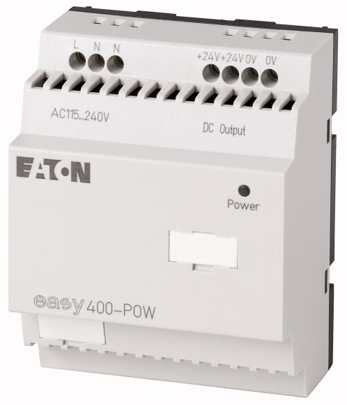
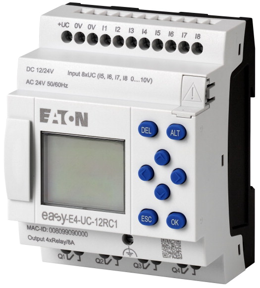
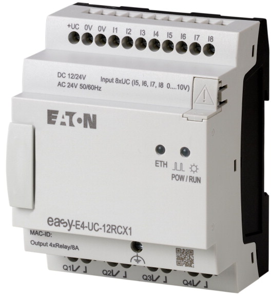
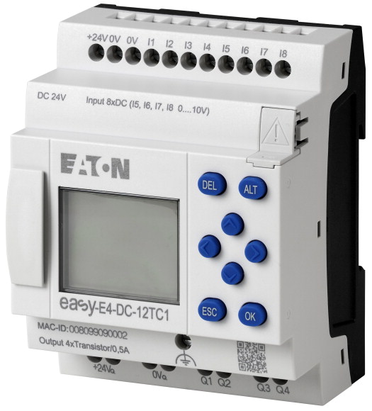
Benzer Ürünler

Aradığınız ürünü bulamıyor musunuz?
SİZE YARDIMCI OLALIM
Aradığınız Ürünü Bulamadınız mı? Bize Bildirin, Sizin İçin Tedarik Edelim!
Web sitemizde yer almayan ya da stokta bulunmayan ürünleri mi arıyorsunuz? İhtiyacınızı bize bildirin, uzman ekibimiz en kısa sürede sizinle iletişime geçerek size en uygun çözümü bulsun.