Eaton : T5-1-102/I5/SVB
207273 T5-1-102/I5/SVB
T5-1-102/I5/SVB /207273
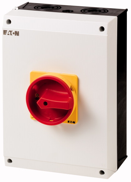
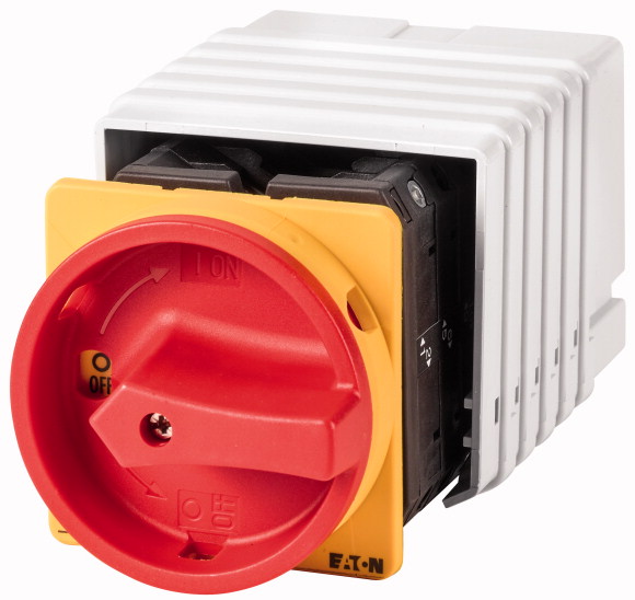
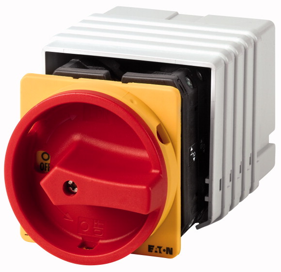
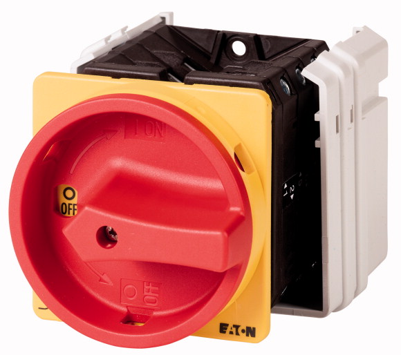
Ana şalter, T5, 100 A, yüzeye montaj, 1 kontak ünitesi/üniteleri, 2 kutuplu, Acil kapatma fonksiyonu, Kırmızı döner kollu ve sarı kilitleme halkalı, 0 (Kapalı) konumunda kilitlenebilir Ana şalter, Ürün yelpazesi: Ana şalter, bakım şalteri, Onarım şalteri, Parça grubu referansı: T5, Durdurma Fonksiyonu: Acil durum kapatma fonksiyonu, Kırmızı döner kollu ve sarı kilitleme halkalı, 2 kutuplu, Kilitleme özelliği: 0 (Kapalı) konumunda kilitlenebilir ) konumu, Koruma Derecesi: IP65, Tasarım: yüzeye montaj, Anahtarlama açısı: 90 °, Motor gücü AC-23A, 50 - 60 Hz 400 V: P = 55 kW, Nominal kesintisiz akım: Iu = 100 A, 1 kontak ünitesi (s), Standartlar: IEC/EN 60947, VDE 0660, IEC/EN 60204, IEC/EN 60947-3'e göre yük ayırıcı
Ana şalter, T5, 100 A, yüzeye montaj, 1 kontak ünitesi/üniteleri, 2 kutuplu, Acil kapatma fonksiyonu, Kırmızı döner kollu ve sarı kilitleme halkalı, 0 (Kapalı) konumunda kilitlenebilir
Ana şalter, Ürün yelpazesi: Ana şalter, bakım şalteri, Onarım şalteri, Parça grubu referansı: T5, Durdurma Fonksiyonu: Acil durum kapatma fonksiyonu, Kırmızı döner kollu ve sarı kilitleme halkalı, 2 kutuplu, Kilitleme özelliği: 0 (Kapalı) konumunda kilitlenebilir ) konumu, Koruma Derecesi: IP65, Tasarım: yüzeye montaj, Anahtarlama açısı: 90 °, Motor gücü AC-23A, 50 - 60 Hz 400 V: P = 55 kW, Nominal kesintisiz akım: Iu = 100 A, 1 kontak ünitesi (s), Standartlar: IEC/EN 60947, VDE 0660, IEC/EN 60204, IEC/EN 60947-3'e göre yük ayırıcı
| Product range | Main switch maintenance switch Repair switch |
| Part group reference | T5 |
| Stop Function | Emergency switching off function |
| Number of poles | With red rotary handle and yellow locking ring |
| Locking facility | 2 pole |
| Degree of Protection | Lockable in the 0 (Off) position |
| Design | IP65 |
| Contact sequence | |
| Switching angle | surface mounting |
| Design number | |
| Function | |
| 400 V [P] | 90 ° |
| Rated uninterrupted current [Iu] | 102 |
| Note on rated uninterrupted current !u | |
| Number of contact units | 55 kW |
| Standards | 100 A |
| Climatic proofing | Rated uninterrupted current Iu is specified for max. cross-section. |
| Ambient temperature >Enclosed |
1 contact unit(s) |
| Overvoltage category/pollution degree | IEC/EN 60947, VDE 0660, IEC/EN 60204 Switch-disconnector according to IEC/EN 60947-3 |
| Rated impulse withstand voltage [Uimp] | Damp heat, constant, to IEC 60068-2-78 Damp heat, cyclic, to IEC 60068-2-30 |
| Mechanical shock resistance | -25 - +40 °C |
| Mounting position | III/3 |
| Mechanical variables >Number of poles |
6000 V AC |
| Electrical characteristics >Rated operational voltage [Ue] |
15 g |
| Electrical characteristics >Rated uninterrupted current [Iu] |
As required |
| Electrical characteristics >Note on rated uninterrupted current !u |
2 pole |
| Load rating with intermittent operation, class 12 >AB 25 % DF |
690 V AC |
| Load rating with intermittent operation, class 12 >AB 40 % DF |
100 A |
| Load rating with intermittent operation, class 12 >AB 60 % DF |
Rated uninterrupted current Iu is specified for max. cross-section. |
| Short-circuit rating >Fuse |
2 x Ie |
| Rated short-time withstand current (1 s current) [Icw ] | 1.6 x Ie |
| Note on rated short-time withstand current lcw | 1.3 x Ie |
| Rated conditional short-circuit current [Iq] | 100 A gG/gL |
| cos ϕ rated making capacity as per IEC 60947-3 | 1700 Arms |
| Rated breaking capacity cos ϕ to IEC 60947-3 >230 V |
Current for a time of 1 second |
| Rated breaking capacity cos ϕ to IEC 60947-3 >400/415 V |
2 kA |
| Rated breaking capacity cos ϕ to IEC 60947-3 >500 V |
950 A |
| Rated breaking capacity cos ϕ to IEC 60947-3 >690 V |
760 A |
| Safe isolation to EN 61140 >between the contacts |
740 A |
| Safe isolation to EN 61140 >Current heat loss per contact at Ie |
590 A |
| Safe isolation to EN 61140 >Current heat loss per auxiliary circuit at Ie (AC-15/230 V) |
420 A |
| Lifespan, mechanical [Operations] | 440 V AC |
| Maximum operating frequency [Operations/h] | 7.5 W |
| AC >AC-3 >Rating, motor load switch [P] >220 V 230 V [P] |
7.5 CO |
| AC >AC-3 >Rating, motor load switch [P] >230 V Star-delta [P] |
> 0.5 x 10⁶ |
| AC >AC-3 >Rating, motor load switch [P] >400 V 415 V [P] |
1200 |
| AC >AC-3 >Rating, motor load switch [P] >400 V Star-delta [P] |
22 kW |
| AC >AC-3 >Rating, motor load switch [P] >500 V [P] |
30 kW |
| AC >AC-3 >Rating, motor load switch [P] >500 V Star-delta [P] |
30 kW |
| AC >AC-3 >Rating, motor load switch [P] >690 V [P] |
45 kW |
| AC >AC-3 >Rating, motor load switch [P] >690 V Star-delta [P] |
30 kW |
| AC >AC-3 >Rated operational current motor load switch >230 V [Ie] |
45 kW |
| AC >AC-3 >Rated operational current motor load switch >230 V star-delta [Ie] |
15 kW |
| AC >AC-3 >Rated operational current motor load switch >400V 415 V [Ie] |
22 kW |
| AC >AC-3 >Rated operational current motor load switch >400 V star-delta [Ie] |
71 A |
| AC >AC-3 >Rated operational current motor load switch >500 V [Ie ] |
100 A |
| AC >AC-3 >Rated operational current motor load switch >500 V star-delta [Ie ] |
55 A |
| AC >AC-3 >Rated operational current motor load switch >690 V [Ie] |
95.3 A |
| AC >AC-3 >Rated operational current motor load switch >690 V star-delta [Ie] |
44 A |
| AC >AC-21A >Rated operational current switch >440 V [Ie] |
76.2 A |
| AC >AC-23A >Motor rating AC-23A, 50 - 60 Hz [P] >230 V [P] |
17 A |
| AC >AC-23A >Motor rating AC-23A, 50 - 60 Hz [P] >400 V 415 V [P] |
29.4 A |
| AC >AC-23A >Motor rating AC-23A, 50 - 60 Hz [P] >500 V [P] |
100 A |
| AC >AC-23A >Motor rating AC-23A, 50 - 60 Hz [P] >690 V [P] |
30 kW |
| AC >AC-23A >Rated operational current motor load switch >230 V [Ie] |
55 kW |
| AC >AC-23A >Rated operational current motor load switch >400 V 415 V [Ie] |
37 kW |
| AC >AC-23A >Rated operational current motor load switch >500 V [Ie] |
30 kW |
| AC >AC-23A >Rated operational current motor load switch >690 V [Ie] |
100 A |
| DC >DC-1, Load-break switches L/R = 1 ms >Rated operational current [Ie] |
100 A |
| DC >DC-1, Load-break switches L/R = 1 ms >Voltage per contact pair in series |
55 A |
| Control circuit reliability at 24 V DC, 10 mA [Fault probability] | 32 A |
| Solid or stranded | 80 A |
| Flexible with ferrules to DIN 46228 | 60 V |
| Terminal screw | < 10 -5, < 1 fault in 100000 operations HF |
| Tightening torque for terminal screw | 1 x (2,5 - 35) 2 x (2,5 - 16) mm2 |
| Notes | 1 x (1 - 25) 2 x (1.5 - 10) mm2 |
| Terminal capacity >Terminal screw |
M6 |
| Terminal capacity >Tightening torque |
4 Nm |
| Rated operational current for specified heat dissipation [In] | B10d values as per EN ISO 13849-1, table C1 |
| Heat dissipation per pole, current-dependent [Pvid] | M6 |
| Equipment heat dissipation, current-dependent [Pvid] | 35.32 lb-in |
| Static heat dissipation, non-current-dependent [Pvs] | 100 A |
| Heat dissipation capacity [Pdiss] | 7.5 W |
| Operating ambient temperature min. | 0 W |
| Operating ambient temperature max. | 0 W |
| 10.2 Strength of materials and parts >10.2.2 Corrosion resistance |
0 W |
| 10.2 Strength of materials and parts >10.2.3.1 Verification of thermal stability of enclosures |
-25 °C |
| 10.2 Strength of materials and parts >10.2.3.2 Verification of resistance of insulating materials to normal heat |
+40 °C |
| 10.2 Strength of materials and parts >10.2.3.3 Verification of resistance of insulating materials to abnormal heat and fire due to internal electric effects |
Meets the product standard´s requirements. |
| 10.2 Strength of materials and parts >10.2.4 Resistance to ultra-violet (UV) radiation |
Meets the product standard´s requirements. |
| 10.2 Strength of materials and parts >10.2.5 Lifting |
Meets the product standard´s requirements. |
| 10.2 Strength of materials and parts >10.2.6 Mechanical impact |
Meets the product standard´s requirements. |
| 10.2 Strength of materials and parts >10.2.7 Inscriptions |
UV resistance only in connection with protective shield. |
| 10.3 Degree of protection of ASSEMBLIES | Does not apply, since the entire switchgear needs to be evaluated. |
| 10.4 Clearances and creepage distances | Does not apply, since the entire switchgear needs to be evaluated. |
| 10.5 Protection against electric shock | Meets the product standard´s requirements. |
| 10.6 Incorporation of switching devices and components | Does not apply, since the entire switchgear needs to be evaluated. |
| 10.7 Internal electrical circuits and connections | Meets the product standard´s requirements. |
| 10.8 Connections for external conductors | Does not apply, since the entire switchgear needs to be evaluated. |
| 10.9 Insulation properties >10.9.2 Power-frequency electric strength |
Does not apply, since the entire switchgear needs to be evaluated. |
| 10.9 Insulation properties >10.9.3 Impulse withstand voltage |
Is the panel builder´s responsibility. |
| 10.9 Insulation properties >10.9.4 Testing of enclosures made of insulating material |
Is the panel builder´s responsibility. |
| 10.10 Temperature rise | Is the panel builder´s responsibility. |
| 10.11 Short-circuit rating | Is the panel builder´s responsibility. |
| 10.12 Electromagnetic compatibility | Is the panel builder´s responsibility. |
| 10.13 Mechanical function | The panel builder is responsible for the temperature rise calculation. Eaton will provide heat dissipation data for the devices. |
| Version as main switch | Is the panel builder´s responsibility. The specifications for the switchgear must be observed. |
| Version as maintenance-/service switch | Is the panel builder´s responsibility. The specifications for the switchgear must be observed. |
| Version as safety switch | The device meets the requirements, provided the information in the instruction leaflet (IL) is observed. |
| Version as emergency stop installation | Yes |
| Version as reversing switch | Yes |
| Number of switches | No |
| Max. rated operation voltage Ue AC | Yes |
| Rated operating voltage | No |
| Rated permanent current Iu | 1 |
| Rated permanent current at AC-23, 400 V | 690 V |
| Rated permanent current at AC-21, 400 V | 690 - 690 V |
| Rated operation power at AC-3, 400 V | 100 A |
| Rated short-time withstand current lcw | 100 A |
| Rated operation power at AC-23, 400 V | 100 A |
| Switching power at 400 V | 30 kW |
| Conditioned rated short-circuit current Iq | 1.7 kA |
| Number of poles | 55 kW |
| Number of auxiliary contacts as normally closed contact | 55 kW |
| Number of auxiliary contacts as normally open contact | 2 kA |
| Number of auxiliary contacts as change-over contact | 2 |
| Motor drive optional | 0 |
| Motor drive integrated | 0 |
| Voltage release optional | 0 |
| Device construction | No |
| Suitable for ground mounting | No |
| Suitable for front mounting 4-hole | No |
| Suitable for front mounting centre | Complete device in housing |
| Suitable for distribution board installation | Yes |
| Suitable for intermediate mounting | No |
| Colour control element | No |
| Type of control element | No |
| Interlockable | No |
| Type of electrical connection of main circuit | Red |
| Degree of protection (IP), front side | Door coupling rotary drive |
| Degree of protection (NEMA) | Yes |
Tüm ürünlerimiz, zorlu çalışma koşullarında dahi maksimum güvenilirlik sunar ve işletmenizin operasyonlarını sorunsuz şekilde sürdürmesine yardımcı olur. Endüstriyel otomasyon, enerji yönetimi, kablolama çözümleri ve daha birçok alanda sunduğumuz ürünler, farklı sektörlerdeki ihtiyaçlara esneklikle uyum sağlar.
Ayrıca, ürünlerimiz sadece kaliteli malzemelerle üretilmiş olup, uluslararası standartlara uygunluk göstermektedir. Müşterilerimize sunduğumuz çözümlerle, operasyonel verimliliklerini artırmalarına ve maliyetlerini optimize etmelerine olanak tanıyoruz. Teknolojik gelişmeleri yakından takip eden firmamız, sürekli olarak yenilikçi ürünler sunarak, müşterilerimizin rekabet avantajı elde etmesine destek vermektedir.
Her bir ürün sayfamızda, teknik detaylar, kullanım alanları ve ürün özelliklerine dair kapsamlı bilgilere ulaşabilirsiniz. Endüstriyel süreçlerinizi güçlendirmek için ihtiyacınız olan tüm ürünleri sitemizden keşfedebilir, sorunsuz bir satın alma deneyimi yaşayabilirsiniz.
Benzer Ürünler
Aradığınız ürünü bulamıyor musunuz?
SİZE YARDIMCI OLALIM
Aradığınız Ürünü Bulamadınız mı? Bize Bildirin, Sizin İçin Tedarik Edelim!
Web sitemizde yer almayan ya da stokta bulunmayan ürünleri mi arıyorsunuz? İhtiyacınızı bize bildirin, uzman ekibimiz en kısa sürede sizinle iletişime geçerek size en uygun çözümü bulsun.