Eaton : XNH2-FCE-S400
183069 XNH2-FCE-S400
XNH2-FCE-S400 /183069
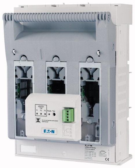
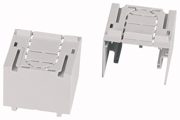
NH sigortalı şalter 3p flanş bağlantısı M10 maks. 240 mm²; bara 60 mm; elektronik sigorta izleme; NH2 NH sigortalı yük ayırıcı 3 kutuplu, M10 düz terminalli maks. 240 mm²; bara 60 mm; elektronik sigorta izleme; NH2 sigorta bağlantıları için; XNH...-SWD-KIT ile smartWire'a hazır; üst/alt kablo bağlantısı saniyeler içinde değiştirilebilir.
NH sigortalı şalter 3p flanş bağlantısı M10 maks. 240 mm²; bara 60 mm; elektronik sigorta izleme; NH2
NH sigortalı yük ayırıcı 3 kutuplu, M10 düz terminalli maks. 240 mm²; bara 60 mm; elektronik sigorta izleme; NH2 sigorta bağlantıları için; XNH...-SWD-KIT ile smartWire'a hazır; üst/alt kablo bağlantısı saniyeler içinde değiştirilebilir.
| Basic function | Fuse control - electronic |
| Number of poles | 3 pole |
| Mounting type | Busbars of 60 mm |
| Size | 2 |
| Type of connection | Flat connection |
| Rated operational current [Ie] | 400 A |
| Front degree of protection (XNH installed) | IP20 (Operating status) IP2XC (Contact protection) IP10 (Handle cover open) |
| Rated operational voltage [Ue ] | 690 V AC |
| Rated operational voltage [Ue] | 440 V DC |
| Rated conditional short-circuit current | 120 (500 V) 100 (690 V) kA |
| Flammability characteristics | Self-extinguishing as per UL 94 |
| Description | Current paths of electrolytic copper, silver-plated Cable connection optionally at the top or bottom With electronic monitoring of fuse-links |
| Standards | IEC/EN 60947-3 |
| Rated operational voltage [Ue ] | 690 V AC |
| Rated operational voltage [Ue] | 440 V DC |
| Rated operational current [Ie] | 400 A |
| Rated frequency [f] | 40 - 60 Hz |
| Rated insulation voltage [Ui] | 800 V AC |
| Total heat dissipation at Ith (without fuses) [Pv] | 36 W |
| Heat dissipation at 80% (without fuses) [Pv] | 22.9 W |
| Rated impulse withstand voltage [Uimp] | 8 kV |
| Utilization category AC-23B >Rated operating voltage [Ue] |
400 V AC |
| Utilization category AC-23B >Rated operating current [Ie] |
400 A |
| Utilization category AC22B >Rated operating voltage [Ue] |
500 V AC |
| Utilization category AC22B >Rated operating current [Ie] |
400 A |
| Utilization category AC-21B >Rated operating voltage [Ue] |
690 V AC |
| Utilization category AC-21B >Rated operating current [Ie] |
400 A |
| Utilization category
DC-22B >Rated operating voltage [Ue] |
DC values on request V DC |
| Utilization category
DC-22B >Rated operating current [Ie] |
DC values on request A |
| Utilization category DC21B >Rated operating voltage [Ue] |
DC values on request V DC |
| Utilization category DC21B >Rated operating current [Ie] |
DC values on request A |
| Rated conditional short-circuit current | 120 (500 V) 100 (690 V) kA |
| Rated short-time withstand current [Icw] | 10 kA |
| Max. fuse >Size according to DIN VDE 0636-2 |
2 |
| Max. fuse >Max. permitted power loss per fuse link [Pv] |
34 W |
| Lifespan, electrical [Operations] | 200 |
| Front degree of protection (XNH installed) | IP20 (Operating status) IP2XC (Contact protection) IP10 (Handle cover open) |
| Ambient temperature | -25 - +55 °C |
| Rated operating mode | Permanent operation |
| Activation | Dependent manual activation |
| Mounting position | Vertical, horizontal |
| Altitude | Max. 2000 m |
| Overvoltage category/pollution degree | III/3 |
| RoHS (in accordance with Directive 2002/95/EC of the European Parliament and Council) | Yes |
| Direction of incoming supply | as required (FLEX System) |
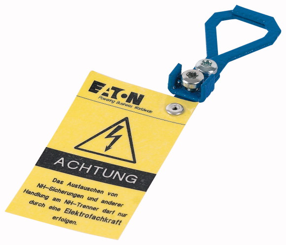
| Lockable | Yes, optional |
| Sealable | Yes, Standard |
| Material characteristics >Material |
Polyamide |
| Material characteristics >Colour |
Grey |
| Flammability characteristics | Self-extinguishing as per UL 94 |
| Halogen-free | Yes |
| Voltage test | Yes, sliding inspection windows |
| Lifespan, mechanical [Operations] | 800 |
| Track resistance | CTI 600 |
| Heat deflection temperature | 125 °C |
| Flange connection >Bolt diameter |
M10 |
| Flange connection >Cable lug max. width |
48 mm |
| Flange connection >Flat busbar |
40 x 10 mm |
| Box terminal >Stranded |
95 - 300 Cu/Al mm2 |
| Box terminal >Copper strip [Number of segments x width x thickness] |
6 x 16 x 0,8 - 10 x 32 x 1 mm |
| Box terminal >Stranded |
25 - 240 Cu mm2 |
| Box terminal >Copper band [Number of segments x width x thickness ] |
10 x 16 x 0,8 mm |
| Clamp-type terminal >Stranded |
120 - 240 Cu/Al mm2 |
| Double clamp-type terminal >Stranded |
2x (120 - 150) Cu/Al mm2 |
| Power supply | Self-supplied |
| Power consumption | 1.5 VA |
| Overvoltage category | 230/400V : III 500V : II |
| Frequency range | 50 - 60 |
| Input resistance | > 1 kOhm/V |
| Voltage inputs | 400 - 500 (+/-10%) V AC |
| Temperature range | -5 - +55 °C |
| Operation indicator | 1 LED green |
| Failure indicator | 3 LEDs (F1, F2, F3) red |
| Degree of protection | IP3X |
| Function test | Test button for relay + LEDs |
| EMC (Electromagnetic compatibility) | IEC 61000-4-4 IEC 61000-4-5 |
| Fuse links | NH with live handle straps |
| Outputs >Relay output |
1 NC 1 NO |
| Outputs >Max. voltage |
250 V AC |
| Outputs >Max. voltage |
24 V DC |
| Outputs >Max. switching current |
1 A |
| Contact sequence | |
| Function diagram | |
| Rated operational current for specified heat dissipation [In] | 400 A |
| Heat dissipation per pole, current-dependent [Pvid] | 7.3 W |
| Equipment heat dissipation, current-dependent [Pvid] | 22 W |
| 10.2 Strength of materials and parts >10.2.2 Corrosion resistance |
Meets the product standard´s requirements. |
| 10.2 Strength of materials and parts >10.2.3.1 Verification of thermal stability of enclosures |
Meets the product standard´s requirements. |
| 10.2 Strength of materials and parts >10.2.3.2 Verification of resistance of insulating materials to normal heat |
Meets the product standard´s requirements. |
| 10.2 Strength of materials and parts >10.2.3.3 Verification of resistance of insulating materials to abnormal heat and fire due to internal electric effects |
Meets the product standard´s requirements. |
| 10.2 Strength of materials and parts >10.2.4 Resistance to ultra-violet (UV) radiation |
Meets the product standard´s requirements. |
| 10.2 Strength of materials and parts >10.2.5 Lifting |
Does not apply, since the entire switchgear needs to be evaluated. |
| 10.2 Strength of materials and parts >10.2.6 Mechanical impact |
Does not apply, since the entire switchgear needs to be evaluated. |
| 10.2 Strength of materials and parts >10.2.7 Inscriptions |
Meets the product standard´s requirements. |
| 10.3 Degree of protection of ASSEMBLIES | Does not apply, since the entire switchgear needs to be evaluated. |
| 10.4 Clearances and creepage distances | Is the panel builder´s responsibility. |
| 10.5 Protection against electric shock | Does not apply, since the entire switchgear needs to be evaluated. |
| 10.6 Incorporation of switching devices and components | Does not apply, since the entire switchgear needs to be evaluated. |
| 10.7 Internal electrical circuits and connections | Is the panel builder´s responsibility. |
| 10.8 Connections for external conductors | Is the panel builder´s responsibility. |
| 10.9 Insulation properties >10.9.2 Power-frequency electric strength |
Ui = 800 V AC |
| 10.9 Insulation properties >10.9.3 Impulse withstand voltage |
Is the panel builder´s responsibility. |
| 10.9 Insulation properties >10.9.4 Testing of enclosures made of insulating material |
Is the panel builder´s responsibility. |
| 10.10 Temperature rise | The panel builder is responsible for the temperature rise calculation. Eaton will provide heat dissipation data for the devices. |
| 10.11 Short-circuit rating | Is the panel builder´s responsibility. The specifications for the switchgear must be observed. |
| 10.12 Electromagnetic compatibility | Is the panel builder´s responsibility. The specifications for the switchgear must be observed. |
| 10.13 Mechanical function | The device meets the requirements, provided the information in the instruction leaflet (IL) is observed. |
| Version as main switch | No |
| Version as safety switch | No |
| Max. rated operation voltage Ue AC | 500 V |
| Rated permanent current Iu | 400 A |
| Rated operation power at AC-23, 400 V | 0 kW |
| Conditioned rated short-circuit current Iq | 120 kA |
| Rated short-time withstand current lcw | 3 kA |
| Suitable for fuses | NH2 |
| Number of poles | 3 |
| With error protection | Yes |
| Type of electrical connection of main circuit | Screw connection |
| Cable entry | Other |
| Equipped with connectors | Yes |
| Suitable for ground mounting | No |
| Suitable for front mounting 4-hole | No |
| Suitable for busbar mounting | Yes |
| Type of control element | Cover grip |
| Position control element | Front side |
| Motor drive optional | No |
| Motor drive integrated | No |
| Version as emergency stop installation | No |
| Degree of protection (IP), front side | Other |
Tüm ürünlerimiz, zorlu çalışma koşullarında dahi maksimum güvenilirlik sunar ve işletmenizin operasyonlarını sorunsuz şekilde sürdürmesine yardımcı olur. Endüstriyel otomasyon, enerji yönetimi, kablolama çözümleri ve daha birçok alanda sunduğumuz ürünler, farklı sektörlerdeki ihtiyaçlara esneklikle uyum sağlar.
Ayrıca, ürünlerimiz sadece kaliteli malzemelerle üretilmiş olup, uluslararası standartlara uygunluk göstermektedir. Müşterilerimize sunduğumuz çözümlerle, operasyonel verimliliklerini artırmalarına ve maliyetlerini optimize etmelerine olanak tanıyoruz. Teknolojik gelişmeleri yakından takip eden firmamız, sürekli olarak yenilikçi ürünler sunarak, müşterilerimizin rekabet avantajı elde etmesine destek vermektedir.
Her bir ürün sayfamızda, teknik detaylar, kullanım alanları ve ürün özelliklerine dair kapsamlı bilgilere ulaşabilirsiniz. Endüstriyel süreçlerinizi güçlendirmek için ihtiyacınız olan tüm ürünleri sitemizden keşfedebilir, sorunsuz bir satın alma deneyimi yaşayabilirsiniz.
Benzer Ürünler

Aradığınız ürünü bulamıyor musunuz?
SİZE YARDIMCI OLALIM
Aradığınız Ürünü Bulamadınız mı? Bize Bildirin, Sizin İçin Tedarik Edelim!
Web sitemizde yer almayan ya da stokta bulunmayan ürünleri mi arıyorsunuz? İhtiyacınızı bize bildirin, uzman ekibimiz en kısa sürede sizinle iletişime geçerek size en uygun çözümü bulsun.