Eaton : PKZ-SOL20
120938 PKZ-SOL20
PKZ-SOL20 /120938
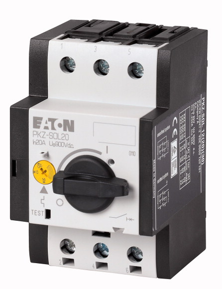
Dizi devre kesici, DC akımı, 2p, 20A PKZ-SOL dizi devre kesiciler, fotovoltaik modüllerin kısa devre akımlarına karşı korunmasına yönelik sigortasız bir alternatiftir. Değişken açma aralıkları sayesinde bir dizinin gerçek kısa devre akımına en uygun şekilde ayarlanabilirler. İsteğe bağlı gecikmeli düşük gerilim bobini P-SOL-XUV kullanılarak, örneğin itfaiye için uzaktan anahtarlama mümkündür.
Dizi devre kesici, DC akımı, 2p, 20A
PKZ-SOL dizi devre kesiciler, fotovoltaik modüllerin kısa devre akımlarına karşı korunmasına yönelik sigortasız bir alternatiftir. Değişken açma aralıkları sayesinde bir dizinin gerçek kısa devre akımına en uygun şekilde ayarlanabilirler. İsteğe bağlı gecikmeli düşük gerilim bobini P-SOL-XUV kullanılarak, örneğin itfaiye için uzaktan anahtarlama mümkündür.
| Product range | Switchgear for photovoltaic systems | ||||||||||||
| Subrange | String circuit-breakers | ||||||||||||
| Product range | String circuit-breakers | ||||||||||||
| Application field | Utility buildings Open areas |
||||||||||||
| Rated operational voltage [Ue] | 900 V | ||||||||||||
| Protection class | 2 | ||||||||||||
| Number of conductors | 2 pole | ||||||||||||
| Rated operational current at DC-21A [Ie] | 20 A | ||||||||||||
| Admissible short-circuit current for solar modules [ISC] | 9 - 15 A | ||||||||||||
| Overload releases >Overload release, min. [Ir] |
|||||||||||||
| Overload releases >Overload release max. |
16 A | ||||||||||||
| Connection technique | 20 A | ||||||||||||
| Design | Screw terminals | ||||||||||||
| Notes | open | ||||||||||||
| Rated operational current at DC-21A [Ie] |
|
||||||||||||
| Number of poles | 20 A | ||||||||||||
| Rated operational voltage [Ue] | 2 pole | ||||||||||||
| Thermal trip | 900 V | ||||||||||||
| Electromagnetic trip block | 1.05 - 1.3 x Ie | ||||||||||||
| Standards | 6 x Ie | ||||||||||||
| Climatic proofing | IEC/EN 60947‐2 TÜV-certified |
||||||||||||
| Open | Damp heat, constant, to IEC 60068-2-78 Damp heat, cyclic, to IEC 60068-2-30 |
||||||||||||
| Mounting position | |||||||||||||
| Width | -25 - +60 °C | ||||||||||||
| Height | |||||||||||||
| Depth | |||||||||||||
| Top-hat rail | 58 mm | ||||||||||||
| Weight | 93 mm | ||||||||||||
| Flexible with ferrule | 76 mm | ||||||||||||
| Solid or stranded | 35 mm | ||||||||||||
| Internal resistance | 0.32 kg | ||||||||||||
| Rated operational current for specified heat dissipation [In] | |||||||||||||
| Heat dissipation per pole, current-dependent [Pvid] | 1 x (1 - 6) 2 x (1 - 6) mm2 |
||||||||||||
| Equipment heat dissipation, current-dependent [Pvid] | 18 - 14 AWG | ||||||||||||
| Static heat dissipation, non-current-dependent [Pvs] | 12 mΩ | ||||||||||||
| Heat dissipation capacity [Pdiss] | |||||||||||||
| Operating ambient temperature min. | 20 A | ||||||||||||
| Operating ambient temperature max. | 1.6 W | ||||||||||||
| 10.2 Strength of materials and parts >10.2.2 Corrosion resistance |
4.8 W | ||||||||||||
| 10.2 Strength of materials and parts >10.2.3.1 Verification of thermal stability of enclosures |
0 W | ||||||||||||
| 10.2 Strength of materials and parts >10.2.3.2 Verification of resistance of insulating materials to normal heat |
0 W | ||||||||||||
| 10.2 Strength of materials and parts >10.2.3.3 Verification of resistance of insulating materials to abnormal heat and fire due to internal electric effects |
-25 °C | ||||||||||||
| 10.2 Strength of materials and parts >10.2.4 Resistance to ultra-violet (UV) radiation |
+60 °C | ||||||||||||
| 10.2 Strength of materials and parts >10.2.5 Lifting |
|||||||||||||
| 10.2 Strength of materials and parts >10.2.6 Mechanical impact |
Meets the product standard´s requirements. | ||||||||||||
| 10.2 Strength of materials and parts >10.2.7 Inscriptions |
Meets the product standard´s requirements. | ||||||||||||
| 10.3 Degree of protection of ASSEMBLIES | Meets the product standard´s requirements. | ||||||||||||
| 10.4 Clearances and creepage distances | Meets the product standard´s requirements. | ||||||||||||
| 10.5 Protection against electric shock | Meets the product standard´s requirements. | ||||||||||||
| 10.6 Incorporation of switching devices and components | Does not apply, since the entire switchgear needs to be evaluated. | ||||||||||||
| 10.7 Internal electrical circuits and connections | Does not apply, since the entire switchgear needs to be evaluated. | ||||||||||||
| 10.8 Connections for external conductors | Meets the product standard´s requirements. | ||||||||||||
| 10.9 Insulation properties >10.9.2 Power-frequency electric strength |
Does not apply, since the entire switchgear needs to be evaluated. | ||||||||||||
| 10.9 Insulation properties >10.9.3 Impulse withstand voltage |
Meets the product standard´s requirements. | ||||||||||||
| 10.9 Insulation properties >10.9.4 Testing of enclosures made of insulating material |
Does not apply, since the entire switchgear needs to be evaluated. | ||||||||||||
| 10.10 Temperature rise | Does not apply, since the entire switchgear needs to be evaluated. | ||||||||||||
| 10.11 Short-circuit rating | Is the panel builder´s responsibility. | ||||||||||||
| 10.12 Electromagnetic compatibility | Is the panel builder´s responsibility. | ||||||||||||
| 10.13 Mechanical function | Is the panel builder´s responsibility. | ||||||||||||
| Rated permanent current Iu | Is the panel builder´s responsibility. | ||||||||||||
| Rated voltage | Is the panel builder´s responsibility. | ||||||||||||
| Rated short-circuit breaking capacity lcu at 400 V, 50 Hz | The panel builder is responsible for the temperature rise calculation. Eaton will provide heat dissipation data for the devices. | ||||||||||||
| Overload release current setting | Is the panel builder´s responsibility. The specifications for the switchgear must be observed. | ||||||||||||
| Adjustment range short-term delayed short-circuit release | Is the panel builder´s responsibility. The specifications for the switchgear must be observed. | ||||||||||||
| Adjustment range undelayed short-circuit release | The device meets the requirements, provided the information in the instruction leaflet (IL) is observed. | ||||||||||||
| Integrated earth fault protection | |||||||||||||
| Type of electrical connection of main circuit | |||||||||||||
| Device construction | 20 A | ||||||||||||
| Suitable for DIN rail (top hat rail) mounting | 900 - 900 V | ||||||||||||
| DIN rail (top hat rail) mounting optional | 0 kA | ||||||||||||
| Number of auxiliary contacts as normally closed contact | 14 - 20 A | ||||||||||||
| Number of auxiliary contacts as normally open contact | 0 - 0 A | ||||||||||||
| Number of auxiliary contacts as change-over contact | 120 - 120 A | ||||||||||||
| With switched-off indicator | No | ||||||||||||
| With under voltage release | Screw connection | ||||||||||||
| Number of poles | Built-in device fixed built-in technique | ||||||||||||
| Position of connection for main current circuit | Yes | ||||||||||||
| Type of control element | Yes | ||||||||||||
| Complete device with protection unit | 0 | ||||||||||||
| Motor drive integrated | 0 | ||||||||||||
| Motor drive optional | 0 | ||||||||||||
| Degree of protection (IP) | No | ||||||||||||
| Specially designed for North America | No | ||||||||||||
| Characteristic curve | 2 |
Tüm ürünlerimiz, zorlu çalışma koşullarında dahi maksimum güvenilirlik sunar ve işletmenizin operasyonlarını sorunsuz şekilde sürdürmesine yardımcı olur. Endüstriyel otomasyon, enerji yönetimi, kablolama çözümleri ve daha birçok alanda sunduğumuz ürünler, farklı sektörlerdeki ihtiyaçlara esneklikle uyum sağlar.
Ayrıca, ürünlerimiz sadece kaliteli malzemelerle üretilmiş olup, uluslararası standartlara uygunluk göstermektedir. Müşterilerimize sunduğumuz çözümlerle, operasyonel verimliliklerini artırmalarına ve maliyetlerini optimize etmelerine olanak tanıyoruz. Teknolojik gelişmeleri yakından takip eden firmamız, sürekli olarak yenilikçi ürünler sunarak, müşterilerimizin rekabet avantajı elde etmesine destek vermektedir.
Her bir ürün sayfamızda, teknik detaylar, kullanım alanları ve ürün özelliklerine dair kapsamlı bilgilere ulaşabilirsiniz. Endüstriyel süreçlerinizi güçlendirmek için ihtiyacınız olan tüm ürünleri sitemizden keşfedebilir, sorunsuz bir satın alma deneyimi yaşayabilirsiniz.
Benzer Ürünler


Aradığınız ürünü bulamıyor musunuz?
SİZE YARDIMCI OLALIM
Aradığınız Ürünü Bulamadınız mı? Bize Bildirin, Sizin İçin Tedarik Edelim!
Web sitemizde yer almayan ya da stokta bulunmayan ürünleri mi arıyorsunuz? İhtiyacınızı bize bildirin, uzman ekibimiz en kısa sürede sizinle iletişime geçerek size en uygun çözümü bulsun.