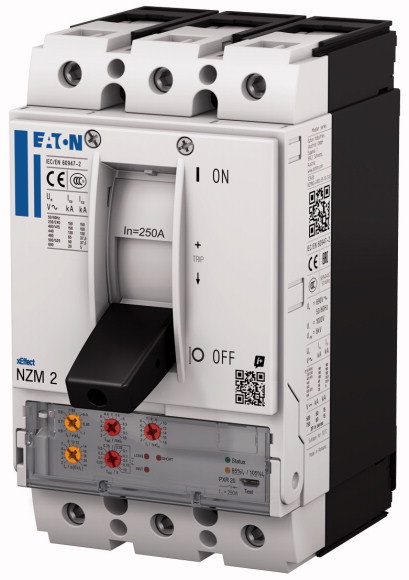
| Description |
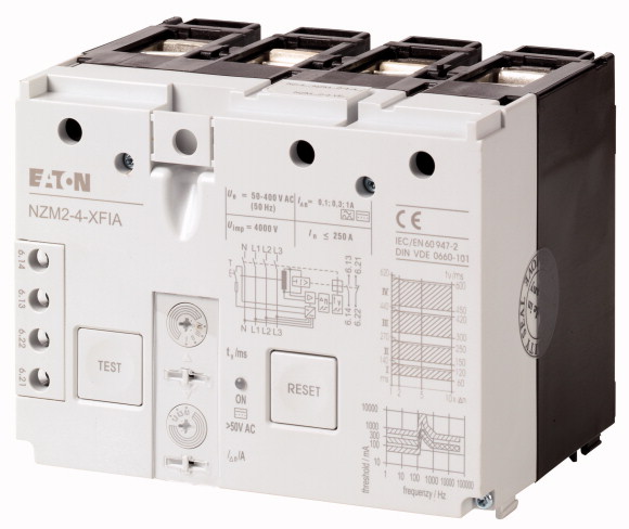
Core-balance principle with AC/DC sensitivity (in range 0 - 100 kHz)
For 4 pole NZM2-4 circuit-breakers and N2-4 switch-disconnectors
Internal power supply Us = 50 - 400 V |
| Contact sequence |
 |
| Contact sequence |
 |
| For use with |
NZM2-4
N2-4 |
| Pole |
4 pole |
| Notes |
Observe response threshold dependence on frequency! See “Frequency response” characteristic curve Auxiliary contacts (1 N/O, 1N/C integrated) are reset via the reset button. Not in combination with plug-in units, insulated enclosure or main switch assembly kit for side panel mounting with mounting bracket. Rated ultimate short-circuit breaking capacity is determined by the fitted NZM2. If a switch-disconnector N2 is applied by the back-up fuse to be used → Technical data. |
| Standards |
IEC/EN 60947-2
IEC/EN 60947-2 annex B |
| Sensitivity |
Sensitive to AC/DC (type B) |
Min. operating voltage [Ue]
>or detection of fault currents type A/AC |
0 V independent of mains voltage |
Min. operating voltage [Ue]
>or detection of fault currents type B |
50 V (dependent on mains voltage) |
| Suitability for the application |
In three- and single-phase systems |
| Rated operational voltage [Ue] |
50…400 (3~) V AC |
| Rated frequency [f] |
50 Hz |
| Number of poles |
4-pole |
| Rated current range [In
] |
15…250 A |
| Rated fault currents [
I
Δn
] |
0.3…0.5…1 A |
| Detection range of the fault current |
with AC voltage: 0 - 100 kHz
with pulsed DC voltage: 50 Hz |
| Rated ultimate short-circuit making capacity and rated ultimate short-circuit breaking capacity [IΔm
] |
= ICU A |
| Mechanical shock resistance (IEC 60068-2-27) |
20 (half-sinusoidal shock 20 ms) |
| Lifespan, mechanical (50 % with fault current) [Operations] |
≧ 2 000 |
| Standard front dimension |
96 mm |
| Mounting |
Bottom |
| Mounting position |
Vertical and 90° in all directions |
| Supply |
Bottom |
| Degree of protection |
IP20 in the operating component area |
| Ambient temperature |
-25 - +70 |
| Sealability |
yes, setting buttons |
Terminal capacity
>Flexible without ferrule |
wie NZM2 Standardanschluss mm2
|
Terminal capacity
>flexible with ferrules |
With NZM2 standard connection mm2
|
| Operating ambient temperature min. |
-25 °C |
| Operating ambient temperature max. |
+70 °C |
10.2 Strength of materials and parts
>10.2.2 Corrosion resistance |
Meets the product standard´s requirements. |
10.2 Strength of materials and parts
>10.2.3.1 Verification of thermal stability of enclosures |
Meets the product standard´s requirements. |
10.2 Strength of materials and parts
>10.2.3.2 Verification of resistance of insulating materials to normal heat |
Meets the product standard´s requirements. |
10.2 Strength of materials and parts
>10.2.3.3 Verification of resistance of insulating materials to abnormal heat and fire due to internal electric effects |
Meets the product standard´s requirements. |
10.2 Strength of materials and parts
>10.2.4 Resistance to ultra-violet (UV) radiation |
Meets the product standard´s requirements. |
10.2 Strength of materials and parts
>10.2.5 Lifting |
Does not apply, since the entire switchgear needs to be evaluated. |
10.2 Strength of materials and parts
>10.2.6 Mechanical impact |
Does not apply, since the entire switchgear needs to be evaluated. |
10.2 Strength of materials and parts
>10.2.7 Inscriptions |
Meets the product standard´s requirements. |
| 10.3 Degree of protection of ASSEMBLIES |
Does not apply, since the entire switchgear needs to be evaluated. |
| 10.4 Clearances and creepage distances |
Meets the product standard´s requirements. |
| 10.5 Protection against electric shock |
Does not apply, since the entire switchgear needs to be evaluated. |
| 10.6 Incorporation of switching devices and components |
Does not apply, since the entire switchgear needs to be evaluated. |
| 10.7 Internal electrical circuits and connections |
Is the panel builder´s responsibility. |
| 10.8 Connections for external conductors |
Is the panel builder´s responsibility. |
10.9 Insulation properties
>10.9.2 Power-frequency electric strength |
Is the panel builder´s responsibility. |
10.9 Insulation properties
>10.9.3 Impulse withstand voltage |
Is the panel builder´s responsibility. |
10.9 Insulation properties
>10.9.4 Testing of enclosures made of insulating material |
Is the panel builder´s responsibility. |
| 10.10 Temperature rise |
The panel builder is responsible for the temperature rise calculation. Eaton will provide heat dissipation data for the devices. |
| 10.11 Short-circuit rating |
Is the panel builder´s responsibility. The specifications for the switchgear must be observed. |
| 10.12 Electromagnetic compatibility |
Is the panel builder´s responsibility. The specifications for the switchgear must be observed. |
| 10.13 Mechanical function |
The device meets the requirements, provided the information in the instruction leaflet (IL) is observed. |
| Rated control supply voltage Us at AC 50HZ |
50 - 400 V |
| Rated control supply voltage Us at AC 60HZ |
50 - 400 V |
| Rated control supply voltage Us at DC |
0 - 0 V |
| Rated fault current |
0.3 - 1 A |
| Max. power on-delay time |
100 ms |
| Delay adjustable |
Yes |
| Max. rated operation voltage Ue |
400 V |
| Characteristic curve |
 |
| Characteristic curve |
Tripping current frequency response
300 mA
SK part no. |
| Characteristic curve |
 |

