Eaton : N2-200-BT
110312 N2-200-BT
N2-200-BT /110312
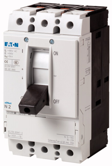
Yük ayırıcı 3p 200A terminalleri Yük ayırıcılar N.. - Topraklanmış IT ağları için bile izolasyon özelliklerine uygundur. Köprü kitleri, bağlantı terminalleri ve kapı birleştirme döner kolları gibi aksesuarlar, çok çeşitli dağıtım sistemlerinde bireysel kuruluma olanak sağlar. Yardımcı anahtarlar, voltaj bobinleri ve uzak operatörler sinyalleşmeyi ve otomasyonu kolaylaştırır. Notlar: IEC/EN 60204 ve VDE 0113'e göre pozitif sürücü dahil ana anahtar özellikleri. IEC/EN 60947-3 ve VDE 0660'a göre izolasyon özellikleri. VDE 0160 Bölüm 100'e göre bara etiket örtüsü.
Yük ayırıcı 3p 200A terminalleri
Yük ayırıcılar N.. - Topraklanmış IT ağları için bile izolasyon özelliklerine uygundur. Köprü kitleri, bağlantı terminalleri ve kapı birleştirme döner kolları gibi aksesuarlar, çok çeşitli dağıtım sistemlerinde bireysel kuruluma olanak sağlar. Yardımcı anahtarlar, voltaj bobinleri ve uzak operatörler sinyalleşmeyi ve otomasyonu kolaylaştırır. Notlar: IEC/EN 60204 ve VDE 0113'e göre pozitif sürücü dahil ana anahtar özellikleri. IEC/EN 60947-3 ve VDE 0660'a göre izolasyon özellikleri. VDE 0160 Bölüm 100'e göre bara etiket örtüsü.
| Product range | Switch-disconnectors | |||||||||||
| Protective function | Disconnectors/main switches | |||||||||||
| Standard/Approval | IEC | |||||||||||
| Installation type | Fixed | |||||||||||
| Construction size | N2 | |||||||||||
| Description | Main switch characteristics including positive drive to IEC/EN 60204 and VDE 0113. Isolating characteristics to IEC/EN 60947-3 and VDE 0660. Busbar tag shroud to VDE 0160 Part 100. |
|||||||||||
| Number of poles | 3 pole | |||||||||||
| Standard equipment | Box terminal | |||||||||||
| Switch positions | I, +, 0 | |||||||||||
| Rated current = rated uninterrupted current [In = Iu] | 200 A | |||||||||||
| Short-circuit protection max. fuse gL-characteristic | 250 A gL | |||||||||||
| Standards | IEC/EN 60947 | |||||||||||
| Protection against direct contact | Finger and back-of-hand proof to DIN EN 50274/VDE 0106 part 110 | |||||||||||
| Climatic proofing | Damp heat, constant, to IEC 60068-2-78 Damp heat, cyclic, to IEC 60068-2-30 |
|||||||||||
| Ambient temperature >Ambient temperature, storage |
- 40 - + 70 °C | |||||||||||
| Ambient temperature >Operation |
-25 - +70 °C | |||||||||||
| Mechanical shock resistance (10 ms half-sinusoidal shock) according to IEC 60068-2-27 | 20 (half-sinusoidal shock 20 ms) g | |||||||||||
| Safe isolation to EN 61140 >Between auxiliary contacts and main contacts |
500 V AC | |||||||||||
| Safe isolation to EN 61140 >between the auxiliary contacts |
300 V AC | |||||||||||
| Mounting position >Mounting position |
|
|||||||||||
| Direction of incoming supply | as required | |||||||||||
| Degree of protection >Device |
In the area of the HMI devices: IP20 (basic protection type) | |||||||||||
| Degree of protection >Enclosures |
With insulating surround: IP40 With door coupling rotary handle: IP66 |
|||||||||||
| Degree of protection >Terminations |
Tunnel terminal: IP10 Phase isolator and band terminal: IP00 |
|||||||||||
| Rated surge voltage invariability [Uimp
] >Main contacts |
8000 V | |||||||||||
| Rated surge voltage invariability [Uimp
] >Auxiliary contacts |
6000 V | |||||||||||
| Rated operational voltage [Ue] | 690 V AC | |||||||||||
| Rated operating frequency [f] | 50/60 Hz | |||||||||||
| Rated current = rated uninterrupted current [In = Iu] | 200 A | |||||||||||
| Overvoltage category/pollution degree | III/3 | |||||||||||
| Rated insulation voltage [Ui ] | 690 V | |||||||||||
| Use in unearthed supply systems | ≦ 690 V | |||||||||||
| Other technical data (sheet catalogue) | Weight Temperature dependency, Derating Effective power loss |
|||||||||||
| 690 V 50/60 H [Ic] | 5.5 kA | |||||||||||
| t = 0.3 s [Icw ] | 3.5 kA | |||||||||||
| t = 1 s [Icw ] | 3.5 kA | |||||||||||
| With back-up fuse | The rated short-time withstand current for PN2/N2 in conjunction with earth-fault release NZM2-4-XFI...Icw = 1.5 kA | |||||||||||
| 400 … 415 V | PN2(N2)-160…250: 250 A gG/gL | |||||||||||
| 690 V | 100 kA | |||||||||||
| With downstream fuse | 80 kA | |||||||||||
| 400 … 415 V | PN2(N2)-160…250: 250 A gG/gL | |||||||||||
| 690 V | 100 kA | |||||||||||
| Rated operational current [Ie
] >AC-22/23A >415 V [Ie] |
80 kA | |||||||||||
| Rated operational current [Ie
] >AC-22/23A >690 V [Ie] |
250 A | |||||||||||
| Lifespan, mechanical [Operations] | 250 A | |||||||||||
| Max. operating frequency | 20000 | |||||||||||
| AC-1 >400 V 50/60 Hz [Operations] |
120 Ops/h | |||||||||||
| AC-1 >415 V 50/60 Hz [Operations] |
10000 | |||||||||||
| AC-1 >690 V 50/60 Hz [Operations] |
10000 | |||||||||||
| AC-3 >400 V 50/60 Hz [Operations] |
7500 | |||||||||||
| AC-3 >415 V 50/60 Hz [Operations] |
7500 | |||||||||||
| AC-3 >690 V 50/60 Hz [Operations] |
7500 | |||||||||||
| Standard equipment | 5000 | |||||||||||
| Optional accessories | Box terminal | |||||||||||
| Copper conductors and cables >Box terminal >Solid |
Screw connection Tunnel terminal connection on rear |
|||||||||||
| Copper conductors and cables >Box terminal >Stranded |
1 x (10 - 16) 2 x (6 - 16) mm2 |
|||||||||||
| Copper conductors and cables >Tunnel terminal >Solid |
1 x (25 - 185) 2 x (25 - 70) mm2 |
|||||||||||
| Copper conductors and cables >Tunnel terminal >Stranded >1-hole |
1 x 16 mm2 | |||||||||||
| Copper conductors and cables >Bolt terminal and rear-side connection >Direct on the switch >Solid |
1 x (25 - 185) mm2 | |||||||||||
| Copper conductors and cables >Bolt terminal and rear-side connection >Direct on the switch >Stranded |
1 x (10 - 16) 2 x (6 - 16) mm2 |
|||||||||||
| Al conductors, Al cable >Tunnel terminal >Solid |
1 x (25 - 185) 2 x (25 - 70) mm2 |
|||||||||||
| Al conductors, Al cable >Tunnel terminal >Stranded >1-hole |
1 x 16 mm2 | |||||||||||
| Al conductors, Al cable >Bolt terminal and rear-side connection >Direct on the switch >Solid |
1 x (25 - 185) mm2 | |||||||||||
| Al conductors, Al cable >Bolt terminal and rear-side connection >Direct on the switch >Stranded |
1 x (10 - 16) 2 x (10 - 16) mm2 |
|||||||||||
| Cu strip (number of segments x width x segment thickness) >Box terminal [min.] |
1 x (25 - 185) 2 x (25 - 70) mm2 |
|||||||||||
| Cu strip (number of segments x width x segment thickness) >Box terminal [max.] |
2 x 9 x 0.8 mm | |||||||||||
| Cu strip (number of segments x width x segment thickness) >Bolt terminal and rear-side connection >Flat copper strip, with holes [min.] |
10 x 16 x 0.8 (2x) 8 x 15.5 x 0,8 mm |
|||||||||||
| Cu strip (number of segments x width x segment thickness) >Bolt terminal and rear-side connection >Flat copper strip, with holes [max.] |
2 x 16 x 0.8 mm | |||||||||||
| Copper busbar (width x thickness) [mm] >Bolt terminal and rear-side connection >Screw connection |
10 x 24 x 0.8 mm | |||||||||||
| Copper busbar (width x thickness) [mm] >Bolt terminal and rear-side connection >Direct on the switch [min.] |
M8 | |||||||||||
| Copper busbar (width x thickness) [mm] >Bolt terminal and rear-side connection >Direct on the switch [max.] |
16 x 5 mm | |||||||||||
| Rated operational current for specified heat dissipation [In] | 24 x 8 mm | |||||||||||
| Equipment heat dissipation, current-dependent [Pvid] | 200 A | |||||||||||
| Operating ambient temperature min. | 30.72 W | |||||||||||
| Operating ambient temperature max. | -25 °C | |||||||||||
| 10.2 Strength of materials and parts >10.2.2 Corrosion resistance |
+70 °C | |||||||||||
| 10.2 Strength of materials and parts >10.2.3.1 Verification of thermal stability of enclosures |
Meets the product standard´s requirements. | |||||||||||
| 10.2 Strength of materials and parts >10.2.3.2 Verification of resistance of insulating materials to normal heat |
Meets the product standard´s requirements. | |||||||||||
| 10.2 Strength of materials and parts >10.2.3.3 Verification of resistance of insulating materials to abnormal heat and fire due to internal electric effects |
Meets the product standard´s requirements. | |||||||||||
| 10.2 Strength of materials and parts >10.2.4 Resistance to ultra-violet (UV) radiation |
Meets the product standard´s requirements. | |||||||||||
| 10.2 Strength of materials and parts >10.2.5 Lifting |
Meets the product standard´s requirements. | |||||||||||
| 10.2 Strength of materials and parts >10.2.6 Mechanical impact |
Does not apply, since the entire switchgear needs to be evaluated. | |||||||||||
| 10.2 Strength of materials and parts >10.2.7 Inscriptions |
Does not apply, since the entire switchgear needs to be evaluated. | |||||||||||
| 10.3 Degree of protection of ASSEMBLIES | Meets the product standard´s requirements. | |||||||||||
| 10.4 Clearances and creepage distances | Does not apply, since the entire switchgear needs to be evaluated. | |||||||||||
| 10.5 Protection against electric shock | Meets the product standard´s requirements. | |||||||||||
| 10.6 Incorporation of switching devices and components | Does not apply, since the entire switchgear needs to be evaluated. | |||||||||||
| 10.7 Internal electrical circuits and connections | Does not apply, since the entire switchgear needs to be evaluated. | |||||||||||
| 10.8 Connections for external conductors | Is the panel builder´s responsibility. | |||||||||||
| 10.9 Insulation properties >10.9.2 Power-frequency electric strength |
Is the panel builder´s responsibility. | |||||||||||
| 10.9 Insulation properties >10.9.3 Impulse withstand voltage |
Is the panel builder´s responsibility. | |||||||||||
| 10.9 Insulation properties >10.9.4 Testing of enclosures made of insulating material |
Is the panel builder´s responsibility. | |||||||||||
| 10.10 Temperature rise | Is the panel builder´s responsibility. | |||||||||||
| 10.11 Short-circuit rating | The panel builder is responsible for the temperature rise calculation. Eaton will provide heat dissipation data for the devices. | |||||||||||
| 10.12 Electromagnetic compatibility | Is the panel builder´s responsibility. The specifications for the switchgear must be observed. | |||||||||||
| 10.13 Mechanical function | Is the panel builder´s responsibility. The specifications for the switchgear must be observed. | |||||||||||
| Version as main switch | The device meets the requirements, provided the information in the instruction leaflet (IL) is observed. | |||||||||||
| Version as maintenance-/service switch | Yes | |||||||||||
| Version as safety switch | Yes | |||||||||||
| Version as emergency stop installation | No | |||||||||||
| Version as reversing switch | Yes | |||||||||||
| Number of switches | No | |||||||||||
| Max. rated operation voltage Ue AC | 1 | |||||||||||
| Rated operating voltage | 690 V | |||||||||||
| Rated permanent current Iu | 690 - 690 V | |||||||||||
| Rated permanent current at AC-23, 400 V | 200 A | |||||||||||
| Rated permanent current at AC-21, 400 V | 0 A | |||||||||||
| Rated operation power at AC-3, 400 V | 0 A | |||||||||||
| Rated short-time withstand current lcw | 0 kW | |||||||||||
| Rated operation power at AC-23, 400 V | 3.5 kA | |||||||||||
| Switching power at 400 V | 110 kW | |||||||||||
| Conditioned rated short-circuit current Iq | 0 kW | |||||||||||
| Number of poles | 0 kA | |||||||||||
| Number of auxiliary contacts as normally closed contact | 3 | |||||||||||
| Number of auxiliary contacts as normally open contact | 0 | |||||||||||
| Number of auxiliary contacts as change-over contact | 0 | |||||||||||
| Motor drive optional | 0 | |||||||||||
| Motor drive integrated | Yes | |||||||||||
| Voltage release optional | No | |||||||||||
| Device construction | Yes | |||||||||||
| Suitable for ground mounting | Built-in device fixed built-in technique | |||||||||||
| Suitable for front mounting 4-hole | Yes | |||||||||||
| Suitable for front mounting centre | No | |||||||||||
| Suitable for distribution board installation | No | |||||||||||
| Suitable for intermediate mounting | Yes | |||||||||||
| Colour control element | Yes | |||||||||||
| Type of control element | Black | |||||||||||
| Interlockable | Rocker lever | |||||||||||
| Type of electrical connection of main circuit | Yes | |||||||||||
| Degree of protection (IP), front side | Frame clamp | |||||||||||
| Degree of protection (NEMA) | IP20 |
Tüm ürünlerimiz, zorlu çalışma koşullarında dahi maksimum güvenilirlik sunar ve işletmenizin operasyonlarını sorunsuz şekilde sürdürmesine yardımcı olur. Endüstriyel otomasyon, enerji yönetimi, kablolama çözümleri ve daha birçok alanda sunduğumuz ürünler, farklı sektörlerdeki ihtiyaçlara esneklikle uyum sağlar.
Ayrıca, ürünlerimiz sadece kaliteli malzemelerle üretilmiş olup, uluslararası standartlara uygunluk göstermektedir. Müşterilerimize sunduğumuz çözümlerle, operasyonel verimliliklerini artırmalarına ve maliyetlerini optimize etmelerine olanak tanıyoruz. Teknolojik gelişmeleri yakından takip eden firmamız, sürekli olarak yenilikçi ürünler sunarak, müşterilerimizin rekabet avantajı elde etmesine destek vermektedir.
Her bir ürün sayfamızda, teknik detaylar, kullanım alanları ve ürün özelliklerine dair kapsamlı bilgilere ulaşabilirsiniz. Endüstriyel süreçlerinizi güçlendirmek için ihtiyacınız olan tüm ürünleri sitemizden keşfedebilir, sorunsuz bir satın alma deneyimi yaşayabilirsiniz.
Benzer Ürünler


Aradığınız ürünü bulamıyor musunuz?
SİZE YARDIMCI OLALIM
Aradığınız Ürünü Bulamadınız mı? Bize Bildirin, Sizin İçin Tedarik Edelim!
Web sitemizde yer almayan ya da stokta bulunmayan ürünleri mi arıyorsunuz? İhtiyacınızı bize bildirin, uzman ekibimiz en kısa sürede sizinle iletişime geçerek size en uygun çözümü bulsun.