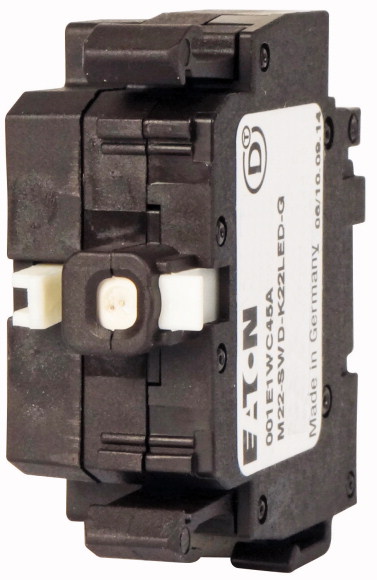
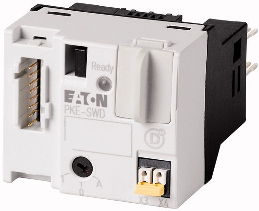
Eaton : M22-SWD-K22LED-W
115978 M22-SWD-K22LED-W
M22-SWD-K22LED-W /115978
Fonksiyon elemanı, RMQ-Titan çalıştırma elemanları M22-... ile kombinasyon için, 2 enversör kontak, Önden sabitleme, beyaz Fonksiyon elemanı, Sabitleme: Önden sabitleme, SmartWire-DT'ye bağlantı: evet
Fonksiyon elemanı, RMQ-Titan çalıştırma elemanları M22-... ile kombinasyon için, 2 enversör kontak, Önden sabitleme, beyaz
Fonksiyon elemanı, Sabitleme: Önden sabitleme, SmartWire-DT'ye bağlantı: evet
Mnelko olarak, endüstriyel otomasyon çözümlerinde güvenilir bir iş ortağı olarak, geniş ürün yelpazesi ile işletmenizin tüm ihtiyaçlarını karşılamaya yönelik kaliteli ve yenilikçi ürünler sunmaktayız. Ürün portföyümüz, modern endüstriyel süreçleri desteklemek amacıyla yüksek performans, dayanıklılık ve verimlilik ilkeleri doğrultusunda tasarlanmış çözümlerden oluşur.
Tüm ürünlerimiz, zorlu çalışma koşullarında dahi maksimum güvenilirlik sunar ve işletmenizin operasyonlarını sorunsuz şekilde sürdürmesine yardımcı olur. Endüstriyel otomasyon, enerji yönetimi, kablolama çözümleri ve daha birçok alanda sunduğumuz ürünler, farklı sektörlerdeki ihtiyaçlara esneklikle uyum sağlar.
Ayrıca, ürünlerimiz sadece kaliteli malzemelerle üretilmiş olup, uluslararası standartlara uygunluk göstermektedir. Müşterilerimize sunduğumuz çözümlerle, operasyonel verimliliklerini artırmalarına ve maliyetlerini optimize etmelerine olanak tanıyoruz. Teknolojik gelişmeleri yakından takip eden firmamız, sürekli olarak yenilikçi ürünler sunarak, müşterilerimizin rekabet avantajı elde etmesine destek vermektedir.
Her bir ürün sayfamızda, teknik detaylar, kullanım alanları ve ürün özelliklerine dair kapsamlı bilgilere ulaşabilirsiniz. Endüstriyel süreçlerinizi güçlendirmek için ihtiyacınız olan tüm ürünleri sitemizden keşfedebilir, sorunsuz bir satın alma deneyimi yaşayabilirsiniz.
Benzer Ürünler
Aradığınız ürünü bulamıyor musunuz?
SİZE YARDIMCI OLALIM
Aradığınız Ürünü Bulamadınız mı? Bize Bildirin, Sizin İçin Tedarik Edelim!
Web sitemizde yer almayan ya da stokta bulunmayan ürünleri mi arıyorsunuz? İhtiyacınızı bize bildirin, uzman ekibimiz en kısa sürede sizinle iletişime geçerek size en uygun çözümü bulsun.

