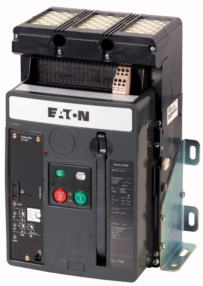
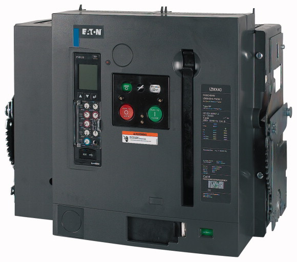
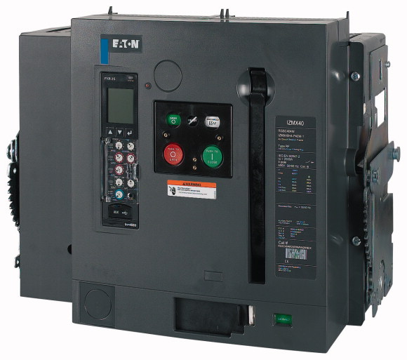
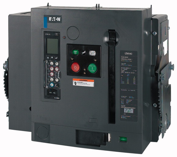
| Product range |
Air circuit-breakers/switch-disconnectors |
| Product range |
Open circuit-breakers |
| Current Range |
Up to 4000 A |
| Protective function |
System protection |
| Installation type |
Fixed |
| Construction size |
IZMX16 |
| Release system |
Electronic release |
| Standard/Approval |
IEC |
| Number of poles |
3 pole |
| Degree of Protection |
IP20, IP55 with protective cover, IP41 door sealing frame |
| Rated current = rated uninterrupted current [In = Iu] |
optionally fittable by user with comprehensive accessories |
| Rated ultimate short-circuit breaking capacity up to 440V/690V 42/42 [Icu
] |
800 A |
| Rated service short-circuit breaking capacity up to 440V/690V 42/42 [Ics
] |
65 kA |
| Overload release, min. [Ir
] |
50 kA |
| Overload release, max. [Ir
] |
400 A |
Non-delayed [Ii = In x …] [Ii = In x …] |
800 A |
| Notes |
2 - 12 |
| Standards |
Main terminals must be separately ordered. |
Ambient temperature
>Storage [ϑ] |
IEC/EN 60947 |
Ambient temperature
>Operating (open) |
-40 - +70 °C |
| Mounting position |
-25 - +70 °C |
| Utilization category |
 |
| Degree of Protection |
 |
| Direction of incoming supply |
B |
| Rated current = rated uninterrupted current [In = Iu] |
IP20, IP55 with protective cover, IP41 door sealing frame |
| Rated uninterrupted current at 50 °C [Iu] |
as required |
| Rated uninterrupted current at 60 °C [Iu] |
800 A |
| Rated uninterrupted current at 70 °C [Iu] |
800 A |
| Rated impulse withstand voltage [Uimp] |
800 A |
| Rated operational voltage [Ue] |
800 A |
| Use in IT electrical power networks up to U = 440 V [IIT
] |
12000 V AC |
| Overvoltage category/pollution degree |
690 V AC |
| Rated insulation voltage [Ui
] |
23 kA |
Rated short-circuit making capacity [Icm
]
>up to 440 V 50/60 Hz [Icm
] |
III/3 |
Rated short-circuit making capacity [Icm
]
>up to 690 V 50/60 Hz [Icm
] |
1000 V |
Rated short-time withstand current 50/60 Hz
>t = 1 s [Icw
] |
136 kA |
Rated short-circuit breaking capacity Icn [Icn
]
>IEC/EN 60947 operating sequence Icu O-t-CO
>up to 240 V 50/60 Hz [Icu
] |
88 kA |
Rated short-circuit breaking capacity Icn [Icn
]
>IEC/EN 60947 operating sequence Icu O-t-CO
>up to 440 V 50/60 Hz [Icu
] |
42 kA |
Rated short-circuit breaking capacity Icn [Icn
]
>IEC/EN 60947 operating sequence Icu O-t-CO
>up to 690 V 50/60 Hz [Icu
] |
85 kA |
Rated short-circuit breaking capacity Icn [Icn
]
>IEC/EN 60947 operating sequence Ics O-t-CO-t-CO
>up to 240 V 50/60 Hz [Ics
] |
65 kA |
Rated short-circuit breaking capacity Icn [Icn
]
>IEC/EN 60947 operating sequence Ics O-t-CO-t-CO
>up to 440 V 50/60 Hz [Ics
] |
42 kA |
Rated short-circuit breaking capacity Icn [Icn
]
>IEC/EN 60947 operating sequence Ics O-t-CO-t-CO
>up to 690 V 50/60 Hz [Ics
] |
65 kA |
Operating times
>Closing delay via spring release |
50 kA |
Operating times
>Total opening delay via shunt release |
42 kA |
Operating times
>Total opening delay via undervoltage release |
30 ms |
Operating times
>Total opening delay on non-delayed short-circuit release (up to complete arc quenching) |
25 ms |
Lifespan
>Lifespan, mechanical [Switching cycles (ON/OFF)] |
50 ms |
Lifespan
>Lifespan, mechanical with maintenance [Switching cycles (ON/OFF)] |
25 ms |
Lifespan
>Lifespan, electrical [Switching cycles (ON/OFF)] |
12500 |
Lifespan
>Lifespan, electrical with maintenance [Switching cycles (ON/OFF)] |
20000 |
| Maximum operating frequency [Operations/h] |
10000 |
Heat dissipation at rated current In
>Fixed mounting |
10000 |
Fixed mounting
>3-pole |
60 |
Fixed mounting
>4-pole |
59 W |
Copper bar
>Fixed mounting
>Black |
19 kg |
Copper bar
>Withdrawable units
>Black |
24 kg |
| Rated operational current for specified heat dissipation [In] |
2 x 5 x 50 mm |
| Equipment heat dissipation, current-dependent [Pvid] |
2 x 5 x 50 mm |
| Operating ambient temperature min. |
These are values used in separate switchgear. The actual values will depend on the temperature around the circuit-breaker, which is influenced by the ambient temperature, the degree of protection (IP), the mounting height, the partitions, and any external ventilation. Depending on the specific switchgear design, this may result in derating, which can then be compensated for by increasing the cross-sectional area. Temperature rise tests in the specific switchgear can provide specific and detailed information. |
| Operating ambient temperature max. |
Permissible continuous current for circuit‐breakers operating in switchboards at various internal ambient temperatures. The switchboard’s internal ambient temperature should be estimated using the calculation methods of IEC regulation. |
10.2 Strength of materials and parts
>10.2.2 Corrosion resistance |
800 A |
10.2 Strength of materials and parts
>10.2.3.1 Verification of thermal stability of enclosures |
59 W |
10.2 Strength of materials and parts
>10.2.3.2 Verification of resistance of insulating materials to normal heat |
-25 °C |
10.2 Strength of materials and parts
>10.2.3.3 Verification of resistance of insulating materials to abnormal heat and fire due to internal electric effects |
+70 °C |
10.2 Strength of materials and parts
>10.2.4 Resistance to ultra-violet (UV) radiation |
Meets the product standard´s requirements. |
10.2 Strength of materials and parts
>10.2.5 Lifting |
Meets the product standard´s requirements. |
10.2 Strength of materials and parts
>10.2.6 Mechanical impact |
Meets the product standard´s requirements. |
10.2 Strength of materials and parts
>10.2.7 Inscriptions |
Meets the product standard´s requirements. |
| 10.3 Degree of protection of ASSEMBLIES |
Meets the product standard´s requirements. |
| 10.4 Clearances and creepage distances |
Does not apply, since the entire switchgear needs to be evaluated. |
| 10.5 Protection against electric shock |
Does not apply, since the entire switchgear needs to be evaluated. |
| 10.6 Incorporation of switching devices and components |
Meets the product standard´s requirements. |
| 10.7 Internal electrical circuits and connections |
Does not apply, since the entire switchgear needs to be evaluated. |
| 10.8 Connections for external conductors |
Meets the product standard´s requirements. |
10.9 Insulation properties
>10.9.2 Power-frequency electric strength |
Does not apply, since the entire switchgear needs to be evaluated. |
10.9 Insulation properties
>10.9.3 Impulse withstand voltage |
Does not apply, since the entire switchgear needs to be evaluated. |
10.9 Insulation properties
>10.9.4 Testing of enclosures made of insulating material |
Is the panel builder´s responsibility. |
| 10.10 Temperature rise |
Is the panel builder´s responsibility. |
| 10.11 Short-circuit rating |
Is the panel builder´s responsibility. |
| 10.12 Electromagnetic compatibility |
Is the panel builder´s responsibility. |
| 10.13 Mechanical function |
Is the panel builder´s responsibility. |
| Rated permanent current Iu |
The panel builder is responsible for the temperature rise calculation. Eaton will provide heat dissipation data for the devices. |
| Rated voltage |
Is the panel builder´s responsibility. The specifications for the switchgear must be observed. |
| Rated short-circuit breaking capacity lcu at 400 V, 50 Hz |
Is the panel builder´s responsibility. The specifications for the switchgear must be observed. |
| Overload release current setting |
The device meets the requirements, provided the information in the instruction leaflet (IL) is observed. |
| Adjustment range short-term delayed short-circuit release |
800 A |
| Adjustment range undelayed short-circuit release |
690 - 690 V |
| Integrated earth fault protection |
65 kA |
| Type of electrical connection of main circuit |
400 - 800 A |
| Device construction |
0 - 0 A |
| Suitable for DIN rail (top hat rail) mounting |
1600 - 9600 A |
| DIN rail (top hat rail) mounting optional |
No |
| Number of auxiliary contacts as normally closed contact |
Rail connection |
| Number of auxiliary contacts as normally open contact |
Built-in device fixed built-in technique |
| Number of auxiliary contacts as change-over contact |
No |
| With switched-off indicator |
No |
| With under voltage release |
0 |
| Number of poles |
0 |
| Position of connection for main current circuit |
2 |
| Type of control element |
Yes |
| Complete device with protection unit |
No |
| Motor drive integrated |
3 |
| Motor drive optional |
Back side |
| Degree of protection (IP) |
Push button |

