Eaton : DILAS-R44(24VDC)
191720 DILAS-R44(24VDC)
DILAS-R44(24VDC) /191720
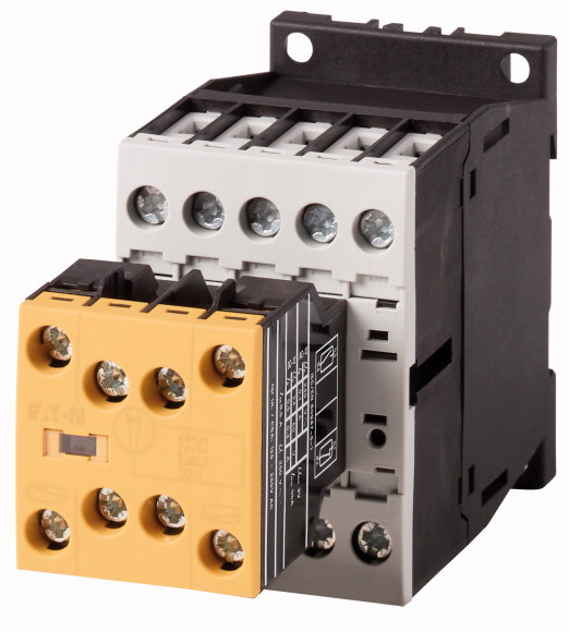
Güvenlik kontaktörü rölesi, 24 V DC, N/O = Normalde açık: 4 N/O, N/C = Normalde kapalı: 4 NC, Vidalı terminaller, DC çalışma Güvenlik kontaktörü rölesi, Uygulama: Kontaktör röleleri, Bağlantı tekniği: Vidalı terminaller, Açıklama: Temel cihazlar ve birbirine kilitli karşılıklı kontaklara sahip üstten montajlı yardımcı kontaklar, (mikro anahtarlar hariç), 2 elektronik uyumlu yardımcı mikro anahtar kontağı (1 NO + 1 NC), Kontaklar N/O = Normalde açık: 4 N/O, Kontaklar N/C = Normalde kapalı: 4 NC, Talimatlar: Kontak numaraları EN 50011'e göre, Bobin terminal işaretleri EN 50005'e göre, dahili baskılayıcı devre', Gerilim AC/DC: DC işlemi
Güvenlik kontaktörü rölesi, 24 V DC, N/O = Normalde açık: 4 N/O, N/C = Normalde kapalı: 4 NC, Vidalı terminaller, DC çalışma
Güvenlik kontaktörü rölesi, Uygulama: Kontaktör röleleri, Bağlantı tekniği: Vidalı terminaller, Açıklama: Temel cihazlar ve birbirine kilitli karşılıklı kontaklara sahip üstten montajlı yardımcı kontaklar, (mikro anahtarlar hariç), 2 elektronik uyumlu yardımcı mikro anahtar kontağı (1 NO + 1 NC), Kontaklar N/O = Normalde açık: 4 N/O, Kontaklar N/C = Normalde kapalı: 4 NC, Talimatlar: Kontak numaraları EN 50011'e göre, Bobin terminal işaretleri EN 50005'e göre, dahili baskılayıcı devre', Gerilim AC/DC: DC işlemi
| Product range | DILAS safety contactor relays |
| Application | Contactor relays |
| Description | Basic devices and top mounting auxiliary contacts with interlocked opposing contacts (except microswitches) 2 electronic-compatible auxiliary microswitch contacts (1 NO + 1 NC) |
| Connection technique | Screw terminals |
| AC-15 >220 V 230 V 240 V [Ie] |
|
| AC-15 >380 V 400 V 415 V [Ie] |
4 A |
| N/O = Normally open | 4 A |
| N/C = Normally closed | |
| Contact sequence | 4 N/O |
| Actuating voltage | 4 NC |
| Voltage AC/DC | |
| Suppressor circuit | 24 V DC |
| Connection to SmartWire-DT | DC operation |
| Instructions | built-in |
| Standards | no |
| Lifespan, mechanical >DC operated [Operations] |
Contact numbers to EN 50011 Coil terminal markings to EN 50005 built-in suppressor circuit´ Integrated varistor suppressor circuit. |
| Maximum operating frequency [Operations/h] | |
| Climatic proofing | IEC/EN 60947, EN 60947-5-1, VDE 0660, UL, CSA |
| Ambient temperature >Open |
20 x 106 |
| Ambient temperature >Enclosed |
9000 |
| Ambient temperature >Ambient temperature, storage |
Damp heat, constant, to IEC 60068-2-78 Damp heat, cyclic, to IEC 60068-2-30 |
| Mounting position >Mounting position |
-25 - +60 °C |
| Mechanical shock resistance (IEC/EN 60068-2-27) >Half-sinusoidal shock, 10 ms >Basic unit with auxiliary contact module >N/O contact |
- 25 - 40 °C |
| Mechanical shock resistance (IEC/EN 60068-2-27) >Half-sinusoidal shock, 10 ms >Basic unit with auxiliary contact module >N/C contact |
- 40 - 80 °C |
| Degree of Protection | |
| Protection against direct contact when actuated from front (EN 50274) | 7 g |
| Altitude | 5 g |
| Weight >DC operated |
IP20 |
| Terminal capacities >Screw terminals >Solid |
Finger and back-of-hand proof |
| Terminal capacities >Screw terminals >Flexible with ferrule |
Max. 2000 m |
| Terminal capacities >Screw terminals >Solid or stranded |
0.344 kg |
| Terminal capacities >Screw terminals >Stripping length |
1 x (0.75 - 4) 2 x (0.75 - 2.5) mm2 |
| Terminal capacities >Screw terminals >Terminal screw |
1 x (0.75 - 2.5) 2 x (0.75 - 2.5) mm2 |
| Terminal capacities >Screw terminals >Pozidriv screwdriver |
18 - 14 AWG |
| Terminal capacities >Screw terminals >Standard screwdriver |
10 mm |
| Terminal capacities >Screw terminals >Max. tightening torque |
M3.5 |
| Positive operating contacts to ZH 1/457, including auxiliary contact module | 2 Size |
| Rated impulse withstand voltage [Uimp] | 0.8 x 5.5 1 x 6 mm |
| Overvoltage category/pollution degree | 1.2 Nm |
| Rated insulation voltage [Ui] | |
| Rated operational voltage [Ue] | Yes |
| Safe isolation to EN 61140 >between coil and auxiliary contacts |
6000 V AC |
| Safe isolation to EN 61140 >between the auxiliary contacts |
III/3 |
| Rated operational current >Conventional free air thermal current, 1 pole >Open >at 60 °C [Ith =Ie] |
690 V AC |
| Rated operational current >AC-15 >220 V 230 V 240 V [Ie] |
690 V AC |
| Rated operational current >AC-15 >380 V 400 V 415 V [Ie] |
400 V AC |
| Rated operational current >AC-15 >500 V [Ie] |
400 V AC |
| Rated operational current >DC current >Notes |
16 A |
| Rated operational current >DC current >DC L/R ≦ 15 ms >Contacts in series: >1 [24 V] |
4 A |
| Rated operational current >DC current >DC L/R ≦ 15 ms >Contacts in series: >1 [60 V] |
4 A |
| Rated operational current >DC current >DC L/R ≦ 15 ms >Contacts in series: >2 [60 V] |
1.5 A |
| Rated operational current >DC current >DC L/R ≦ 15 ms >Contacts in series: >1 [110 V] |
Switch-on and switch-off conditions based on DC-13, time constant as specified. |
| Rated operational current >DC current >DC L/R ≦ 15 ms >Contacts in series: >3 [110 V] |
10 A |
| Rated operational current >DC current >DC L/R ≦ 15 ms >Contacts in series: >1 [220 V] |
6 A |
| Rated operational current >DC current >DC L/R ≦ 15 ms >Contacts in series: >3 [220 V] |
10 A |
| Rated operational current >DC current >DC L/R ≦ 50 ms >Contacts in series: >3 [24 V] |
3 A |
| Rated operational current >DC current >DC L/R ≦ 50 ms >Contacts in series: >3 [60 V] |
6 A |
| Rated operational current >DC current >DC L/R ≦ 50 ms >Contacts in series: >3 [110 V] |
1 A |
| Rated operational current >DC current >DC L/R ≦ 50 ms >Contacts in series: >3 [220 V] |
5 A |
| Short-circuit rating without welding >Maximum overcurrent protective device >220 V 230 V 240 V |
4 A |
| Short-circuit rating without welding >Maximum overcurrent protective device >380 V 400 V 415 V |
4 A |
| Short-circuit rating without welding >Short-circuit protection maximum fuse >500 V |
2 A |
| Current heat loss at Ith >DC operated |
1 A |
| Voltage tolerance >DC operated >Notes |
4 PKZM0 |
| Voltage tolerance >DC operated >Pick-up voltage |
4 PKZM0 |
| Power consumption >DC operation >DC operated [Pull-in = sealing] |
10 A gG/gL |
| duty factor | 1.07 W |
| Changeover time at 100 % US (recommended value) >DC operated closing delay >Switching times, DC operated, max. closing delay |
|
| Changeover time at 100 % US (recommended value) >DC operated N/O contact opening delay >Switching times, DC actuated make contact Opening delay, max. |
Smoothed DC, three-phase bridge rectifiers or smoothed double-wave rectification |
| Auxiliary contacts >Pilot Duty >AC operated |
0.8 - 1.1 |
| Auxiliary contacts >Pilot Duty >DC operated |
3 W |
| Auxiliary contacts >General Use >AC |
100 % DF |
| Auxiliary contacts >General Use >AC |
31 ms |
| Auxiliary contacts >General Use >DC |
12 ms |
| Auxiliary contacts >General Use >DC |
|
| Further information | A600 |
| Rated operational current for specified heat dissipation [In] | P300 |
| Heat dissipation per pole, current-dependent [Pvid] | 600 V |
| Equipment heat dissipation, current-dependent [Pvid] | 15 A |
| Static heat dissipation, non-current-dependent [Pvs] | 250 V |
| Heat dissipation capacity [Pdiss] | 1 A |
| Operating ambient temperature min. | |
| Operating ambient temperature max. | → auxiliary contact component DILA-XHIR22 (139580) |
| 10.2 Strength of materials and parts >10.2.2 Corrosion resistance |
|
| 10.2 Strength of materials and parts >10.2.3.1 Verification of thermal stability of enclosures |
15.5 A |
| 10.2 Strength of materials and parts >10.2.3.2 Verification of resistance of insulating materials to normal heat |
1 W |
| 10.2 Strength of materials and parts >10.2.3.3 Verification of resistance of insulating materials to abnormal heat and fire due to internal electric effects |
0 W |
| 10.2 Strength of materials and parts >10.2.4 Resistance to ultra-violet (UV) radiation |
3 W |
| 10.2 Strength of materials and parts >10.2.5 Lifting |
0 W |
| 10.2 Strength of materials and parts >10.2.6 Mechanical impact |
-25 °C |
| 10.2 Strength of materials and parts >10.2.7 Inscriptions |
+60 °C |
| 10.3 Degree of protection of ASSEMBLIES | |
| 10.4 Clearances and creepage distances | Meets the product standard´s requirements. |
| 10.5 Protection against electric shock | Meets the product standard´s requirements. |
| 10.6 Incorporation of switching devices and components | Meets the product standard´s requirements. |
| 10.7 Internal electrical circuits and connections | Meets the product standard´s requirements. |
| 10.8 Connections for external conductors | Meets the product standard´s requirements. |
| 10.9 Insulation properties >10.9.2 Power-frequency electric strength |
Does not apply, since the entire switchgear needs to be evaluated. |
| 10.9 Insulation properties >10.9.3 Impulse withstand voltage |
Does not apply, since the entire switchgear needs to be evaluated. |
| 10.9 Insulation properties >10.9.4 Testing of enclosures made of insulating material |
Meets the product standard´s requirements. |
| 10.10 Temperature rise | Does not apply, since the entire switchgear needs to be evaluated. |
| 10.11 Short-circuit rating | Meets the product standard´s requirements. |
| 10.12 Electromagnetic compatibility | Does not apply, since the entire switchgear needs to be evaluated. |
| 10.13 Mechanical function | Does not apply, since the entire switchgear needs to be evaluated. |
| Rated control supply voltage Us at AC 50HZ | Is the panel builder´s responsibility. |
| Rated control supply voltage Us at AC 60HZ | Is the panel builder´s responsibility. |
| Rated control supply voltage Us at DC | Is the panel builder´s responsibility. |
| Voltage type for actuating | Is the panel builder´s responsibility. |
| Rated operation current Ie, 400 V | Is the panel builder´s responsibility. |
| Connection type auxiliary circuit | The panel builder is responsible for the temperature rise calculation. Eaton will provide heat dissipation data for the devices. |
| Mounting method | Is the panel builder´s responsibility. The specifications for the switchgear must be observed. |
| Interface | Is the panel builder´s responsibility. The specifications for the switchgear must be observed. |
| Number of auxiliary contacts as normally closed contact | The device meets the requirements, provided the information in the instruction leaflet (IL) is observed. |
| Number of auxiliary contacts as normally open contact | |
| Number of auxiliary contacts as normally closed contact, delayed switching | |
| Number of auxiliary contacts as normally open contact, leading | 0 - 0 V |
| With LED indication | 0 - 0 V |
| Number of auxiliary contacts as change-over contact | 24 - 24 V |
| Manual operation possible | DC |
| Product Standards | 4 A |
| UL File No. | Screw connection |
| UL Category Control No. | DIN-rail/screw |
| CSA File No. | No |
| CSA Class No. | 4 |
| North America Certification | 4 |
| Specially designed for North America | 0 |
| Accessories | 0 |
| Characteristic curve | No |
| Characteristic curve | 0 |
Tüm ürünlerimiz, zorlu çalışma koşullarında dahi maksimum güvenilirlik sunar ve işletmenizin operasyonlarını sorunsuz şekilde sürdürmesine yardımcı olur. Endüstriyel otomasyon, enerji yönetimi, kablolama çözümleri ve daha birçok alanda sunduğumuz ürünler, farklı sektörlerdeki ihtiyaçlara esneklikle uyum sağlar.
Ayrıca, ürünlerimiz sadece kaliteli malzemelerle üretilmiş olup, uluslararası standartlara uygunluk göstermektedir. Müşterilerimize sunduğumuz çözümlerle, operasyonel verimliliklerini artırmalarına ve maliyetlerini optimize etmelerine olanak tanıyoruz. Teknolojik gelişmeleri yakından takip eden firmamız, sürekli olarak yenilikçi ürünler sunarak, müşterilerimizin rekabet avantajı elde etmesine destek vermektedir.
Her bir ürün sayfamızda, teknik detaylar, kullanım alanları ve ürün özelliklerine dair kapsamlı bilgilere ulaşabilirsiniz. Endüstriyel süreçlerinizi güçlendirmek için ihtiyacınız olan tüm ürünleri sitemizden keşfedebilir, sorunsuz bir satın alma deneyimi yaşayabilirsiniz.
Benzer Ürünler


Aradığınız ürünü bulamıyor musunuz?
SİZE YARDIMCI OLALIM
Aradığınız Ürünü Bulamadınız mı? Bize Bildirin, Sizin İçin Tedarik Edelim!
Web sitemizde yer almayan ya da stokta bulunmayan ürünleri mi arıyorsunuz? İhtiyacınızı bize bildirin, uzman ekibimiz en kısa sürede sizinle iletişime geçerek size en uygun çözümü bulsun.