Eaton : DA1-12011FB-A20C
169084 DA1-12011FB-A20C
DA1-12011FB-A20C /169084
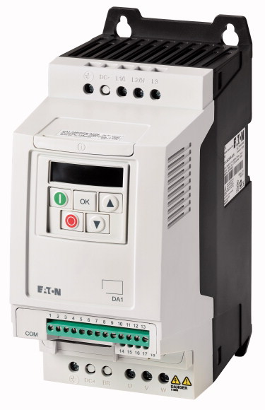
Değişken frekanslı sürücü, 230 V AC, 1 fazlı, 10,5 A, 2,2 kW, IP20/NEMA 0, Radyo parazitini giderme filtresi, 7 dijital ekran aksamı Değişken frekanslı sürücü, Parça grubu referansı (örn. DIL): DA1, Nominal çalışma gerilimi: Ue = 230 V AC, 1 fazlı, 240 V AC, tek fazlı, Ve ile çıkış gerilimi: U2 = 230 V AC, 3 fazlı , 240 V AC, 3 faz, Şebeke voltajı (50/60Hz): ULN = 200 (-%10) - 240 (+%10) V, Nominal çalışma akımı %150 aşırı yükte: Ie = 10,5 A, Not: Nominal 16 kHz çalışma frekansında ve +50 °C ortam hava sıcaklığında çalışma akımı, Not: Her 600 saniyede 60 saniyelik aşırı yük döngüsü, Atanan motor gücü Not: normal dahili ve harici havalandırmalı 4 kutuplu, üç fazlı asenkron motorlar için 50 Hz'de 1500 rpm-1 veya 60 Hz'de 1800 dk-1, 230 V, 50 Hz'de her 600 saniyede 60 saniyelik aşırı yük döngüsü, Atanan motor gücü %150 Aşırı yük: P = 2,2 kW, %150 Aşırı yük: IM = 8,7 A, Atanan motor gücü Not: 220 - 240 V, 60 Hz'de, Atanan motor gücü %150 Aşırı yük: P = 3 HP, Atanan motor gücü %150 Aşırı yük: IM = 9,6 A, Koruma Derecesi: IP20/NEMA 0 , Arayüz/field bus (dahili): OP-Bus (RS485)/Modbus RTU, CANopen®, Fieldbus bağlantısı (opsiyonel): Ethernet IP, DeviceNet, PROFIBUS, PROFINET, Modbus-TCP, EtherCAT, SmartWire-DT, Takılı Şunlarla: Radyo parazitini bastırma filtresi, Fren kıyıcı, Ek PCB koruması, 7 dijital ekran aksamı, Çerçeve boyutu: FS2, Standartlar: Genel gereksinimler için spesifikasyon: IEC/EN 61800-2, EMC gereksinimleri: IEC/EN 61800-3, Güvenlik gereksinimler: IEC/EN 61800-5-1
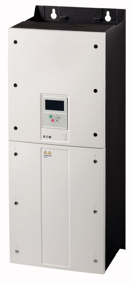
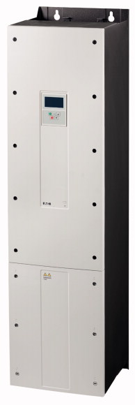
Değişken frekanslı sürücü, 230 V AC, 1 fazlı, 10,5 A, 2,2 kW, IP20/NEMA 0, Radyo parazitini giderme filtresi, 7 dijital ekran aksamı
Değişken frekanslı sürücü, Parça grubu referansı (örn. DIL): DA1, Nominal çalışma gerilimi: Ue = 230 V AC, 1 fazlı, 240 V AC, tek fazlı, Ve ile çıkış gerilimi: U2 = 230 V AC, 3 fazlı , 240 V AC, 3 faz, Şebeke voltajı (50/60Hz): ULN = 200 (-%10) - 240 (+%10) V, Nominal çalışma akımı %150 aşırı yükte: Ie = 10,5 A, Not: Nominal 16 kHz çalışma frekansında ve +50 °C ortam hava sıcaklığında çalışma akımı, Not: Her 600 saniyede 60 saniyelik aşırı yük döngüsü, Atanan motor gücü Not: normal dahili ve harici havalandırmalı 4 kutuplu, üç fazlı asenkron motorlar için 50 Hz'de 1500 rpm-1 veya 60 Hz'de 1800 dk-1, 230 V, 50 Hz'de her 600 saniyede 60 saniyelik aşırı yük döngüsü, Atanan motor gücü %150 Aşırı yük: P = 2,2 kW, %150 Aşırı yük: IM = 8,7 A, Atanan motor gücü Not: 220 - 240 V, 60 Hz'de, Atanan motor gücü %150 Aşırı yük: P = 3 HP, Atanan motor gücü %150 Aşırı yük: IM = 9,6 A, Koruma Derecesi: IP20/NEMA 0 , Arayüz/field bus (dahili): OP-Bus (RS485)/Modbus RTU, CANopen®, Fieldbus bağlantısı (opsiyonel): Ethernet IP, DeviceNet, PROFIBUS, PROFINET, Modbus-TCP, EtherCAT, SmartWire-DT, Takılı Şunlarla: Radyo parazitini bastırma filtresi, Fren kıyıcı, Ek PCB koruması, 7 dijital ekran aksamı, Çerçeve boyutu: FS2, Standartlar: Genel gereksinimler için spesifikasyon: IEC/EN 61800-2, EMC gereksinimleri: IEC/EN 61800-3, Güvenlik gereksinimler: IEC/EN 61800-5-1
| Product range | Variable frequency drives |
| Part group reference (e.g. DIL) | DA1 |
| Rated operational voltage [Ue] | 230 V AC, 1-phase 240 V AC, single-phase |
| Output voltage with Ve [U2] | 230 V AC, 3-phase 240 V AC, 3-phase |
| Mains voltage (50/60Hz) [ULN] | 200 (-10%) - 240 (+10%) V |
| At 150% overload [Ie] | |
| Note | 10.5 A |
| Note | Rated operational current at an operating frequency of 16 kHz and an ambient air temperature of +50 °C |
| Note | |
| Note | for normal internally and externally ventilated 4 pole, three-phase asynchronous motors with 1500 rpm-1 at 50 Hz or 1800 min-1 at 60 Hz |
| 150 % Overload [P] | Overload cycle for 60 s every 600 s |
| 150 % Overload [IM] | at 230 V, 50 Hz |
| Note | 2.2 kW |
| 150 % Overload [P] | 8.7 A |
| 150 % Overload [IM] | at 220 - 240 V, 60 Hz |
| Degree of Protection | 3 HP |
| Interface/field bus (built-in) | 9.6 A |
| Fieldbus connection (optional) | IP20/NEMA0 |
| Fitted with | OP-Bus (RS485)/Modbus RTU, CANopen® |
| Parameterization | Ethernet IP DeviceNet PROFIBUS PROFINET Modbus-TCP EtherCAT SmartWire-DT |
| Frame size | Radio interference suppression filter Brake chopper Additional PCB protection 7-digital display assembly |
| Connection to SmartWire-DT | Keypad Fieldbus drivesConnect drivesConnect mobile (App) |
| Standards | FS2 |
| Certifications | yes in conjunction with DX-NET-SWD1 SmartWire DT module |
| Production quality | |
| Climatic proofing [ρw] | Specification for general requirements: IEC/EN 61800-2 EMC requirements: IEC/EN 61800-3 Safety requirements: IEC/EN 61800-5-1 |
| Air quality | CE, UL, cUL, RCM, UkrSEPRO, EAC |
| Ambient temperature >Operating ambient temperature min. |
RoHS, ISO 9001 |
| Ambient temperature >Operating ambient temperature max. |
< 95%, average relative humidity (RH), non-condensing, non-corrosive % |
| Ambient temperature | 3C2, 3S2 |
| Ambient temperature >Storage [ϑ] |
-10 °C |
| Radio interference level >Radio interference class (EMC) |
+50 °C |
| Radio interference level >Environment (EMC) |
operation (with 150 % overload) |
| Radio interference level >maximum motor cable length [I] |
-40 - +60 °C |
| Mounting position | C1 (for conducted emissions only), C2, C3, depending on the motor cable length, the connected load, and ambient conditions. External radio interference suppression filters (optional) may be necessary. |
| Altitude | 1st and 2nd environments as per EN 61800-3 |
| Degree of Protection | C1 ≤ 1 m C2 ≤ 5 m C3 ≤ 25 m m |
| Protection against direct contact | Vertical |
| Supply >Rated operational voltage [Ue] |
0 - 1000 m above sea level Above 1000 m: 1% derating for every 100 m max. 4000 m m |
| Supply >Mains voltage (50/60Hz) [ULN] |
IP20/NEMA0 |
| Supply >Input current (150% overload) [ILN] |
BGV A3 (VBG4, finger- and back-of-hand proof) |
| Supply >System configuration |
|
| Supply >Supply frequency [fLN] |
230 V AC, 1-phase 240 V AC, single-phase |
| Supply >Frequency range [fLN] |
200 (-10%) - 240 (+10%) V |
| Supply >Mains switch-on frequency |
19.2 A |
| Power section >Function |
AC supply systems with earthed center point |
| Power section >Overload current (150% overload) [IL] |
50/60 Hz |
| Power section >max. starting current (High Overload) [IH] |
48 - 62 Hz |
| Power section >Note about max. starting current |
Maximum of one time every 30 seconds |
| Power section >Output voltage with Ve [U2] |
Variable frequency drive with internal DC link and IGBT inverter |
| Power section >Output Frequency [f2] |
15.75 A |
| Power section >Switching frequency [fPWM] |
200 % |
| Power section >Operation Mode |
for 4 seconds every 40 seconds |
| Power section >Frequency resolution (setpoint value) [Δf] |
230 V AC, 3-phase 240 V AC, 3-phase |
| Power section >Rated operational current >At 150% overload [Ie] |
0 - 50/60 (max. 500) Hz |
| Power section >Note |
16 adjustable 4 - 32 (audible) kHz |
| Power section >Power loss >Heat dissipation at rated operational current Ie =150 % [PV] |
U/f control Speed control with slip compensation sensorless vector control (SLV) optional: Vector control with feedback (CLV) |
| Power section >Efficiency [η] |
0.1 Hz |
| Power section >Maximum leakage current to ground (PE) without motor [IPE] |
10.5 A |
| Power section >Fitted with |
Rated operational current at an operating frequency of 16 kHz and an ambient air temperature of +50 °C |
| Power section >Safety function |
103.4 W |
| Power section >Frame size |
95.3 % |
| Motor feeder >Note |
2.49 mA |
| Motor feeder >Note |
Radio interference suppression filter Brake chopper Additional PCB protection 7-digital display assembly |
| Motor feeder >Note |
STO (Safe Torque Off, SIL2, PLd Cat 3) |
| Motor feeder >150 % Overload [P] |
FS2 |
| Motor feeder >Note |
for normal internally and externally ventilated 4 pole, three-phase asynchronous motors with 1500 rpm-1 at 50 Hz or 1800 min-1 at 60 Hz |
| Motor feeder >150 % Overload [P] |
Overload cycle for 60 s every 600 s |
| Motor feeder >maximum permissible cable length [I] |
at 230 V, 50 Hz |
| Motor feeder >Apparent power >Apparent power at rated operation 230 V [S] |
2.2 kW |
| Motor feeder >Apparent power >Apparent power at rated operation 240 V [S] |
at 220 - 240 V, 60 Hz |
| Motor feeder >Braking function >Standard braking torque |
3 HP |
| Motor feeder >Braking function >DC braking torque |
screened: 100 screened, with motor choke: 200 unscreened: 150 unscreened, with motor choke: 300 m |
| Motor feeder >Braking function >Braking torque with external braking resistance |
4.18 kVA |
| Motor feeder >Braking function >minimum external braking resistance [Rmin] |
4.36 kVA |
| Motor feeder >Braking function >Switch-on threshold for the braking transistor [UDC] |
max. 30 % MN |
| External control voltage [Uc] | max. 100% of rated operational current Ie, variable |
| Reference voltage [Us] | Max. 100% of rated operational current Ie with external braking resistor |
| Analog inputs | 35 Ω |
| Analog outputs | 390 V DC V |
| Digital inputs | |
| Digital outputs | 24 V DC (max. 100 mA) V |
| Relay outputs | 10 V DC (max. 10 mA) V |
| Interface/field bus (built-in) | 2, parameterizable, 0 - 10 V DC, 0/4 - 20 mA |
| Power Wiring >Safety device (fuse or miniature circuit-breaker) >IEC (Type B, gG), 150 % |
2, parameterizable, 0 - 10 V, 0/4 - 20 mA |
| Power Wiring >Safety device (fuse or miniature circuit-breaker) >UL (Class CC or J) |
3, parameterizable, max. 30 VDC, max. 5 for non-parameterized analog inputs |
| Power Wiring >Mains contactor >150 % overload (CT/IH, at 50 °C) |
2, parameterizable, 24 V DC |
| Power Wiring >Main choke >150 % overload (CT/IH, at 50 °C) |
2, parameterizable, 1 N/O and 1 changeover contact, 6 A (250 V, AC-1) / 5 A (30 V, DC-1) |
| Power Wiring >Radio interference suppression filter (external, 150 %) |
OP-Bus (RS485)/Modbus RTU, CANopen® |
| Power Wiring >Note regarding radio interference suppression filter |
|
| DC link connection >Braking resistance >10 % duty factor (DF) |
FAZ-B25/1N |
| DC link connection >Braking resistance >20 % duty factor (DF) |
25 A |
| DC link connection >Braking resistance >40 % duty factor (DF) |
DILM7 |
| DC link connection >Braking resistance >Notes concerning braking resistances: |
DX-LN1-024 |
| Motor feeder >motor choke >150 % overload (CT/IH, at 50 °C) |
DX-EMC12-025-FS2 |
| Motor feeder >Sine filter >150 % overload (CT/IH, at 50 °C) |
Optional external radio interference suppression filter for longer motor cable lengths and for use in different EMC environments |
| Motor feeder >All-pole sine filter >150 % overload (CT/IH, at 50 °C) |
DX-BR050-0K4 |
| Rated operational current for specified heat dissipation [In] | DX-BR050-0K8 |
| Heat dissipation per pole, current-dependent [Pvid] | DX-BR035-1K1 |
| Equipment heat dissipation, current-dependent [Pvid] | The brake resistors are assigned based on the maximum rated power of the variable frequency drive. Additional brake resistors and designs (e.g. different duty cycles) are available upon request. |
| Static heat dissipation, non-current-dependent [Pvs] | DX-LM3-016 |
| Heat dissipation capacity [Pdiss] | DX-SIN3-016 |
| Operating ambient temperature min. | DX-SIN3-013-A |
| Operating ambient temperature max. | |
| 10.2 Strength of materials and parts >10.2.2 Corrosion resistance |
10.5 A |
| 10.2 Strength of materials and parts >10.2.3.1 Verification of thermal stability of enclosures |
0 W |
| 10.2 Strength of materials and parts >10.2.3.2 Verification of resistance of insulating materials to normal heat |
103.4 W |
| 10.2 Strength of materials and parts >10.2.3.3 Verification of resistance of insulating materials to abnormal heat and fire due to internal electric effects |
0 W |
| 10.2 Strength of materials and parts >10.2.4 Resistance to ultra-violet (UV) radiation |
0 W |
| 10.2 Strength of materials and parts >10.2.5 Lifting |
-10 °C |
| 10.2 Strength of materials and parts >10.2.6 Mechanical impact |
+50 °C |
| 10.2 Strength of materials and parts >10.2.7 Inscriptions |
|
| 10.3 Degree of protection of ASSEMBLIES | Meets the product standard´s requirements. |
| 10.4 Clearances and creepage distances | Meets the product standard´s requirements. |
| 10.5 Protection against electric shock | Meets the product standard´s requirements. |
| 10.6 Incorporation of switching devices and components | Meets the product standard´s requirements. |
| 10.7 Internal electrical circuits and connections | Meets the product standard´s requirements. |
| 10.8 Connections for external conductors | Does not apply, since the entire switchgear needs to be evaluated. |
| 10.9 Insulation properties >10.9.2 Power-frequency electric strength |
Does not apply, since the entire switchgear needs to be evaluated. |
| 10.9 Insulation properties >10.9.3 Impulse withstand voltage |
Meets the product standard´s requirements. |
| 10.9 Insulation properties >10.9.4 Testing of enclosures made of insulating material |
Does not apply, since the entire switchgear needs to be evaluated. |
| 10.10 Temperature rise | Meets the product standard´s requirements. |
| 10.11 Short-circuit rating | Does not apply, since the entire switchgear needs to be evaluated. |
| 10.12 Electromagnetic compatibility | Does not apply, since the entire switchgear needs to be evaluated. |
| 10.13 Mechanical function | Is the panel builder´s responsibility. |
| Mains voltage | Is the panel builder´s responsibility. |
| Mains frequency | Is the panel builder´s responsibility. |
| Number of phases input | Is the panel builder´s responsibility. |
| Number of phases output | Is the panel builder´s responsibility. |
| Max. output frequency | The panel builder is responsible for the temperature rise calculation. Eaton will provide heat dissipation data for the devices. |
| Max. output voltage | Is the panel builder´s responsibility. The specifications for the switchgear must be observed. |
| Nominal output current I2N | Is the panel builder´s responsibility. The specifications for the switchgear must be observed. |
| Max. output at quadratic load at rated output voltage | The device meets the requirements, provided the information in the instruction leaflet (IL) is observed. |
| Max. output at linear load at rated output voltage | |
| Relative symmetric net frequency tolerance | |
| Relative symmetric net voltage tolerance | 180 - 264 V |
| Number of analogue outputs | 50/60 Hz |
| Number of analogue inputs | 1 |
| Number of digital outputs | 3 |
| Number of digital inputs | 500 Hz |
| With control unit | 250 V |
| Application in industrial area permitted | 10.5 A |
| Application in domestic- and commercial area permitted | 2.2 kW |
| Supporting protocol for TCP/IP | 2.2 kW |
| Supporting protocol for PROFIBUS | 10 % |
| Supporting protocol for CAN | 10 % |
| Supporting protocol for INTERBUS | 2 |
| Supporting protocol for ASI | 2 |
| Supporting protocol for KNX | 2 |
| Supporting protocol for MODBUS | 5 |
| Supporting protocol for Data-Highway | Yes |
| Supporting protocol for DeviceNet | Yes |
| Supporting protocol for SUCONET | Yes |
| Supporting protocol for LON | Yes |
| Supporting protocol for PROFINET IO | Yes |
| Supporting protocol for PROFINET CBA | Yes |
| Supporting protocol for SERCOS | No |
| Supporting protocol for Foundation Fieldbus | No |
| Supporting protocol for EtherNet/IP | No |
| Supporting protocol for AS-Interface Safety at Work | Yes |
| Supporting protocol for DeviceNet Safety | No |
| Supporting protocol for INTERBUS-Safety | Yes |
| Supporting protocol for PROFIsafe | No |
| Supporting protocol for SafetyBUS p | No |
| Supporting protocol for BACnet | Yes |
| Supporting protocol for other bus systems | No |
| Number of HW-interfaces industrial Ethernet | No |
| Number of interfaces PROFINET | No |
| Number of HW-interfaces RS-232 | Yes |
| Number of HW-interfaces RS-422 | No |
| Number of HW-interfaces RS-485 | No |
| Number of HW-interfaces serial TTY | No |
| Number of HW-interfaces USB | No |
| Number of HW-interfaces parallel | No |
| Number of HW-interfaces other | Yes |
| With optical interface | Yes |
| With PC connection | 0 |
| Integrated breaking resistance | 0 |
| 4-quadrant operation possible | 0 |
| Type of converter | 0 |
| Degree of protection (IP) | 1 |
| Degree of protection (NEMA) | 0 |
| Height | 0 |
| Width | 0 |
| Depth | 0 |
| Product Standards | No |
| UL File No. | Yes |
| UL Category Control No. | Yes |
| CSA File No. | No |
| North America Certification | U converter |
| Specially designed for North America | IP20 |
| Suitable for | Other |
| Max. Voltage Rating | 231 mm |
| Degree of Protection | 107 mm |
Tüm ürünlerimiz, zorlu çalışma koşullarında dahi maksimum güvenilirlik sunar ve işletmenizin operasyonlarını sorunsuz şekilde sürdürmesine yardımcı olur. Endüstriyel otomasyon, enerji yönetimi, kablolama çözümleri ve daha birçok alanda sunduğumuz ürünler, farklı sektörlerdeki ihtiyaçlara esneklikle uyum sağlar.
Ayrıca, ürünlerimiz sadece kaliteli malzemelerle üretilmiş olup, uluslararası standartlara uygunluk göstermektedir. Müşterilerimize sunduğumuz çözümlerle, operasyonel verimliliklerini artırmalarına ve maliyetlerini optimize etmelerine olanak tanıyoruz. Teknolojik gelişmeleri yakından takip eden firmamız, sürekli olarak yenilikçi ürünler sunarak, müşterilerimizin rekabet avantajı elde etmesine destek vermektedir.
Her bir ürün sayfamızda, teknik detaylar, kullanım alanları ve ürün özelliklerine dair kapsamlı bilgilere ulaşabilirsiniz. Endüstriyel süreçlerinizi güçlendirmek için ihtiyacınız olan tüm ürünleri sitemizden keşfedebilir, sorunsuz bir satın alma deneyimi yaşayabilirsiniz.
Benzer Ürünler


Aradığınız ürünü bulamıyor musunuz?
SİZE YARDIMCI OLALIM
Aradığınız Ürünü Bulamadınız mı? Bize Bildirin, Sizin İçin Tedarik Edelim!
Web sitemizde yer almayan ya da stokta bulunmayan ürünleri mi arıyorsunuz? İhtiyacınızı bize bildirin, uzman ekibimiz en kısa sürede sizinle iletişime geçerek size en uygun çözümü bulsun.