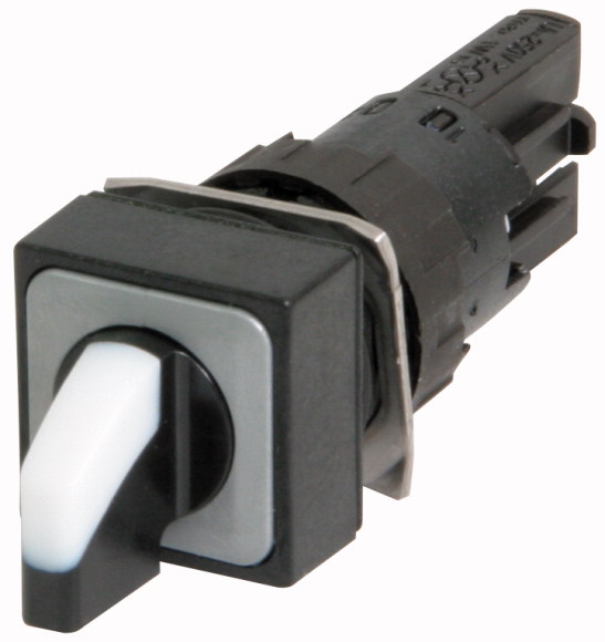
Selector switch, 2 positions, white, momentaryChangeover switch, Product range: RMQ16, Single unit, Design: With thumb-grip, momentary, with VS anti-rotation tab, 2 positions, Colour Thumb-grip: White, Degree of Protection: IP65, without bezel, Connection to SmartWire-DT: no, Front dimensions: Front dimensions 18 × 18 mm, Degree of Protection: IP65
Selector switch, 2 positions, white, momentary
Changeover switch, Product range: RMQ16, Single unit, Design: With thumb-grip, momentary, with VS anti-rotation tab, 2 positions, Colour Thumb-grip: White, Degree of Protection: IP65, without bezel, Connection to SmartWire-DT: no, Front dimensions: Front dimensions 18 × 18 mm, Degree of Protection: IP65
| Product range | RMQ16 |
| Basic function | Selector switch actuators |
| Single unit/Complete unit | Single unit |
| Design | With thumb-grip |
| Description | momentary |
| Thumb-grip |  45° 45° |
| Degree of Protection | with VS anti-rotation tab |
| Front ring | 2 positions |
| Connection to SmartWire-DT | White |
| Front dimensions | |
| Standards | IP65 |
| Lifespan, mechanical [Operations] | without bezel |
| Operating frequency [Operations/h] | no |
| Operating torque | Front dimensions 18 × 18 mm |
| Degree of protection, IEC/EN 60529 | IEC/EN 60947 |
| Climatic proofing | > 3 x 10⁶ |
| Ambient temperature >Open |
≦ 1800 |
| Ambient temperature >Enclosed |
≦ 0.2 Nm |
| Mounting position | IP65 |
| Mechanical shock resistance | Damp heat, constant, to IEC 60068-2-78 Damp heat, cyclic, to IEC 60068-2-30 |
| Terminal capacities | -25 - +60 °C |
| Blade terminal | - 25 - 40 °C |
| Fast-on connectors | As required |
| Rated impulse withstand voltage [Uimp] | > 40 according to IEC 60068-2-27 Shock duration 11 ms Sinusoidal g |
| Rated insulation voltage [Ui ] | 0.5 - 1.0 mm2 |
| Overvoltage category/pollution degree | 2.8 x 0.8 mm to DIN 46244 |
| Rated operational voltage [Ue] | 2.8 x 0.8 mm to DIN 46247 and IEC 60760 |
| Control circuit reliability >at 24 V DC/5 mA [HF ] |
800 V AC |
| Control circuit reliability >at 5 V DC/1 mA [HF ] |
250 V |
| Use of insulated ferrule ISH 2,8 | III/3 |
| Rated operational current for specified heat dissipation [In] | 24 V AC |
| Heat dissipation per pole, current-dependent [Pvid] | < 10-7, < 1 failure in 107 operations Fault probability |
| Equipment heat dissipation, current-dependent [Pvid] | < 5 x 10⁻⁶, < 1 failure in 5 x 10⁶ operations Fault probability |
| Static heat dissipation, non-current-dependent [Pvs] | On >24 V AC/DC recommended On >50 V AC or 120 V DC mandatory, also on unoccupied blade terminals |
| Heat dissipation capacity [Pdiss] | 0 A |
| Operating ambient temperature min. | 0 W |
| Operating ambient temperature max. | 0 W |
| 10.2 Strength of materials and parts >10.2.2 Corrosion resistance |
0 W |
| 10.2 Strength of materials and parts >10.2.3.1 Verification of thermal stability of enclosures |
0 W |
| 10.2 Strength of materials and parts >10.2.3.2 Verification of resistance of insulating materials to normal heat |
-25 °C |
| 10.2 Strength of materials and parts >10.2.3.3 Verification of resistance of insulating materials to abnormal heat and fire due to internal electric effects |
+60 °C |
| 10.2 Strength of materials and parts >10.2.4 Resistance to ultra-violet (UV) radiation |
Meets the product standard´s requirements. |
| 10.2 Strength of materials and parts >10.2.5 Lifting |
Meets the product standard´s requirements. |
| 10.2 Strength of materials and parts >10.2.6 Mechanical impact |
Meets the product standard´s requirements. |
| 10.2 Strength of materials and parts >10.2.7 Inscriptions |
Meets the product standard´s requirements. |
| 10.3 Degree of protection of ASSEMBLIES | Please enquire |
| 10.4 Clearances and creepage distances | Does not apply, since the entire switchgear needs to be evaluated. |
| 10.5 Protection against electric shock | Does not apply, since the entire switchgear needs to be evaluated. |
| 10.6 Incorporation of switching devices and components | Meets the product standard´s requirements. |
| 10.7 Internal electrical circuits and connections | Does not apply, since the entire switchgear needs to be evaluated. |
| 10.8 Connections for external conductors | Meets the product standard´s requirements. |
| 10.9 Insulation properties >10.9.2 Power-frequency electric strength |
Does not apply, since the entire switchgear needs to be evaluated. |
| 10.9 Insulation properties >10.9.3 Impulse withstand voltage |
Does not apply, since the entire switchgear needs to be evaluated. |
| 10.9 Insulation properties >10.9.4 Testing of enclosures made of insulating material |
Is the panel builder´s responsibility. |
| 10.10 Temperature rise | Is the panel builder´s responsibility. |
| 10.11 Short-circuit rating | Is the panel builder´s responsibility. |
| 10.12 Electromagnetic compatibility | Is the panel builder´s responsibility. |
| 10.13 Mechanical function | Is the panel builder´s responsibility. |
| Number of switch positions | Not applicable. |
| Type of control element | Is the panel builder´s responsibility. The specifications for the switchgear must be observed. |
| Suitable for illumination | Is the panel builder´s responsibility. The specifications for the switchgear must be observed. |
| Colour control element | The device meets the requirements, provided the information in the instruction leaflet (IL) is observed. |
| Colour indicator light cap | 2 |
| Construction type lens | Toggle |
| Hole diameter | No |
| Width opening | White |
| Height opening | Other |
| Switching function latching | Square |
| Spring-return | 16 mm |
| With front ring | 0 mm |
| Material front ring | 0 mm |
| Colour front ring | No |
| Degree of protection (IP), front side | Yes |
| Degree of protection (NEMA) | Yes |
| Product Standards | Plastic |
| UL File No. | Black |
| UL Category Control No. | IP65 |
| CSA File No. | 1 |
| CSA Class No. | IEC/EN 60947-5; UL 508; CSA-C22.2 No. 14-05; CE marking |
| North America Certification | E29184 |
| Degree of Protection | NKCR |
Tüm hakları saklıdır. Mnelko Endüstriyel San. ve Tic.Ltd.Şti. 2024