Sick : FLOWSIC100 Flare
FLOWSIC100 Flare
FLOWSIC100 Flare
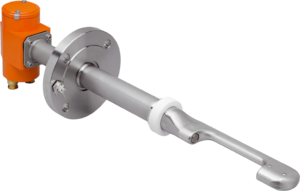
The FLOWSIC100 Flare product family is designed for flare gas and steam flow measurements. The product family is characterized by a unique flow-optimized sensor design. This innovative design minimizes flow-generated noise and signal drift when gas velocities are particularly high. Modern signal processing and high-efficiency transducers enable high time resolution for signals and thus deliver accurate measurements, even at extremely low gas flow rates.The standard system configuration includes two sender/receiver units or one measuring probe and the MCUP control unit. The MCUP unit is used to input and output signals; to calculate reference values (normalization), molecular weight and mass flow; to record gas volumes; and to provide user-friendly control via the LCD display.At a glanceHigh-resolution measurement and short response timeInnovative sensor design for very high gas velocities and gas temperatures up to 280 °COptimal signal transmission even under atmospheric pressureDetached installation of the control unit up to 1,000 m awaySingle and multi-path configuration, opt. Probe versionZero point test in the field according to factory standardControl cycle for automatic self-diagnosis / signal optimizationYour benefitsReliable process control due to exact measurement near the zero point High measurement availability even in the case of emergency shutdowns with gas velocities of up to 120 m/s A solution for the measurement of flare gas and steam injection Cost savings due to detached installation of the control unit possible in the safe area System solution for the control of three different measuring points with a common control unit Cost savings due to one-sided installation when using FLOWSIC100 EX-PR probe version Optimal device performance due to continual function monitoring and extended diagnostic functions in the field
The FLOWSIC100 Flare product family is designed for flare gas and steam flow measurements. The product family is characterized by a unique flow-optimized sensor design. This innovative design minimizes flow-generated noise and signal drift when gas velocities are particularly high. Modern signal processing and high-efficiency transducers enable high time resolution for signals and thus deliver accurate measurements, even at extremely low gas flow rates.
The standard system configuration includes two sender/receiver units or one measuring probe and the MCUP control unit. The MCUP unit is used to input and output signals; to calculate reference values (normalization), molecular weight and mass flow; to record gas volumes; and to provide user-friendly control via the LCD display.
At a glanceHigh-resolution measurement and short response timeInnovative sensor design for very high gas velocities and gas temperatures up to 280 °COptimal signal transmission even under atmospheric pressureDetached installation of the control unit up to 1,000 m awaySingle and multi-path configuration, opt. Probe versionZero point test in the field according to factory standardControl cycle for automatic self-diagnosis / signal optimizationYour benefitsReliable process control due to exact measurement near the zero point High measurement availability even in the case of emergency shutdowns with gas velocities of up to 120 m/s A solution for the measurement of flare gas and steam injection Cost savings due to detached installation of the control unit possible in the safe area System solution for the control of three different measuring points with a common control unit Cost savings due to one-sided installation when using FLOWSIC100 EX-PR probe version Optimal device performance due to continual function monitoring and extended diagnostic functions in the field| Measured values | Mass flow rate, volumetric flow s. c. (standard condition), volumetric flow a. c. (actual condition), molecular weight, gas volume and mass, gas velocity, gas temperature, sound velocity | |||||||||
| Number of measuring paths | 1, 2 | |||||||||
| Measurement principle | Ultrasonic transit time difference measurement, ASC-Technology (active sound correlation) | |||||||||
| Measuring medium | Typical flare gas | |||||||||
| Measuring ranges | 0,03 m/s ... 120 m/s 1 | |||||||||
| Measuring span | Up to 4000:1 1 | |||||||||
| Repeatability | (acc. to ISO 5725-1; JCGM 200:2012): < 0.5 % of the measured value in the range ≥ 1 m/s | |||||||||
| Resolution | (acc. to JCGM 200:2012): + 0.001 m/s | |||||||||
| ||||||||||
| ||||||||||
| ||||||||||
| ||||||||||
| ||||||||||
| Storage temperature | –40 °C ... +70 °C –50 °C ... +70 °C | |||||||||
| Ambient humidity | ≤ 95 % Relative humidity | |||||||||
| Electrical safety | CE | |||||||||
| Footnote | 1) 2) 3) 4) 5) |
1) 1 Depending on application conditions, such as gas composition, process temperature, device type, pipe diameter, etc. To be evaluated by SICK.
2) 2 For ultrasonic transit time difference measurement with fully developed flow profile.
3) 3 The exemplary uncertainty statement acc. to GUM (Guide to the Expression of Uncertainty in Measurement): ISO/IEC Guide 98-3:2008-09 assumes a gas temperature of 20 °C, ambient pressure, a typical molecular weight greater than 27 g/mol and a pipe diameter greater than 8″.
4) 4 Depending on the capabilities of the selected flow lab.
5) 5 Additional measurement uncertainty. In the range of 100 % - 130 % of the last gas velocity measured with ultrasonic transit time difference measurement.
All of our products ensure maximum reliability even in challenging working conditions and help your business operations run smoothly. The products we offer in industrial automation, energy management, cabling solutions, and many other areas adapt flexibly to the needs of different sectors.
Additionally, our products are manufactured using only high-quality materials and comply with international standards. Through the solutions we provide, we enable our customers to increase operational efficiency and optimize costs. Our company closely follows technological advancements and continuously offers innovative products to help our customers gain a competitive advantage.
On each of our product pages, you can find comprehensive information about technical details, areas of use, and product features. You can explore all the products you need to strengthen your industrial processes on our website and enjoy a seamless purchasing experience.
Similar Products
Can't find the product you're looking for?
LET US HELP YOU
Can't Find the Product You're Looking For? Let Us Know, and We'll Source It for You!
Are you searching for products not listed on our website or out of stock? Let us know your requirements, and our expert team will contact you as soon as possible to find the most suitable solution for you.