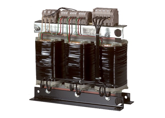
Product range |
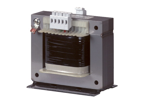
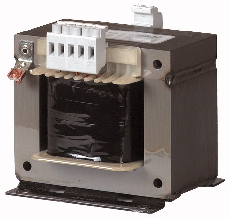
Single-phase control transformers ST... |
Basic function |
Single-phase control, isolating and safety transformers STI, STZ |
Rated input voltage |
230± 5 % V |
Rated output voltage |
230 V |
Rated power |
0.2 kVA |
Short-time rating |
0.44 kVA |
Terminal diagram / contact assignment |
|
Cu factor |
0,65 kg |
Standards >Built and tested to |
|
Standards >Suitable for use to |
IEC/EN 61558-2-2/2-4/2-6 VDE 0570 Part 2-2 VDE 0570 Part 2‐6 (safety transformers) VDE 0570 Part 2-4 (isolating transformer) |
Ambient temperature |
IEC/EN 60204-1, ÖVE-EN 13 VDE 0113, VDE 0100 Part 410 |
Terminations |
-25 - 40 |
Connection lugs |
|
Insulation class |
● (< 115 A) |
Rated frequency |
● (> 115 A) |
Primary tapping |
B |
Degree of Protection |
50 - 60 Hz |
Separate windings |
± 5 % |
Fully vacuum-impregnated |
IP00 |
Reinforced insulation |
● |
Rated duty factor |
● |
Note |
● |
Total weight |
100 % DF |
No-load losses |
|
Short-circuit losses |
The following applies for the no-load loss, short-circuit loss (copper losses), short-circuit voltage and efficiency values: all details relate to a temperature of 20 °C |
Shortcircuit voltage |
3 kg |
Efficiency |
11 W |
Rated operational current for specified heat dissipation [In] |
17 W |
Heat dissipation per pole, current-dependent [Pvid] |
6.6 % |
Equipment heat dissipation, current-dependent [Pvid] |
0.88 |
Static heat dissipation, non-current-dependent [Pvs] |
|
Heat dissipation capacity [Pdiss] |
0 A |
Operating ambient temperature min. |
0 W |
Operating ambient temperature max. |
0 W |
10.2 Strength of materials and parts >10.2.2 Corrosion resistance |
28 W |
10.2 Strength of materials and parts >10.2.3.1 Verification of thermal stability of enclosures |
0 W |
10.2 Strength of materials and parts >10.2.3.2 Verification of resistance of insulating materials to normal heat |
-25 °C |
10.2 Strength of materials and parts >10.2.3.3 Verification of resistance of insulating materials to abnormal heat and fire due to internal electric effects |
+40 °C |
10.2 Strength of materials and parts >10.2.4 Resistance to ultra-violet (UV) radiation |
|
10.2 Strength of materials and parts >10.2.5 Lifting |
Meets the product standard´s requirements. |
10.2 Strength of materials and parts >10.2.6 Mechanical impact |
Meets the product standard´s requirements. |
10.2 Strength of materials and parts >10.2.7 Inscriptions |
Meets the product standard´s requirements. |
10.3 Degree of protection of ASSEMBLIES |
Meets the product standard´s requirements. |
10.4 Clearances and creepage distances |
Meets the product standard´s requirements. |
10.5 Protection against electric shock |
Does not apply, since the entire switchgear needs to be evaluated. |
10.6 Incorporation of switching devices and components |
Does not apply, since the entire switchgear needs to be evaluated. |
10.7 Internal electrical circuits and connections |
Meets the product standard´s requirements. |
10.8 Connections for external conductors |
Does not apply, since the entire switchgear needs to be evaluated. |
10.9 Insulation properties >10.9.2 Power-frequency electric strength |
Meets the product standard´s requirements. |
10.9 Insulation properties >10.9.3 Impulse withstand voltage |
Does not apply, since the entire switchgear needs to be evaluated. |
10.9 Insulation properties >10.9.4 Testing of enclosures made of insulating material |
Does not apply, since the entire switchgear needs to be evaluated. |
10.10 Temperature rise |
Is the panel builder´s responsibility. |
10.11 Short-circuit rating |
Is the panel builder´s responsibility. |
10.12 Electromagnetic compatibility |
Is the panel builder´s responsibility. |
10.13 Mechanical function |
Is the panel builder´s responsibility. |
Built as safety transformer |
Is the panel builder´s responsibility. |
Built as isolating transformer |
The panel builder is responsible for the temperature rise calculation. Eaton will provide heat dissipation data for the devices. |
Built as energy saving transformer |
Is the panel builder´s responsibility. The specifications for the switchgear must be observed. |
Primary voltage 1 |
Is the panel builder´s responsibility. The specifications for the switchgear must be observed. |
Primary voltage 2 |
The device meets the requirements, provided the information in the instruction leaflet (IL) is observed. |
Primary voltage 3 |
|
Primary voltage 4 |
|
Primary voltage 5 |
Yes |
Primary voltage 6 |
Yes |
Primary voltage 7 |
No |
Primary voltage 8 |
230 - 230 V |
Primary voltage 9 |
0 - 0 V |
Primary voltage 10 |
0 - 0 V |
Secondary voltage 1 |
0 - 0 V |
Secondary voltage 2 |
0 - 0 V |
Secondary voltage 3 |
0 - 0 V |
Secondary voltage 4 |
0 - 0 V |
Secondary voltage 5 |
0 - 0 V |
Secondary voltage 6 |
0 - 0 V |
Secondary voltage 7 |
0 - 0 V |
Secondary voltage 8 |
230 - 230 V |
Secondary voltage 9 |
0 - 0 V |
Secondary voltage 10 |
0 - 0 V |
Rated apparent power |
0 - 0 V |
Type of insulation material acc. IEC 85 |
0 - 0 V |
Short-circuit-proof |
0 - 0 V |
Relative short circuit voltage |
0 - 0 V |
Width |
0 - 0 V |
Height |
0 - 0 V |
Depth |
0 - 0 V |
Degree of protection (IP) |
200 VA |
Ring core |
B |
Suitable for mounting on PCB |
No |
Modular version |
6.6 % |
Conductor material |
106 mm |
Product Standards |
124 mm |
UL File No. |
83 mm |
UL Category Control No. |
IP00 |
CSA File No. |
No |
CSA Class No. |
No |
North America Certification |
No |
Specially designed for North America |
Copper |
Suitable for |
UL 506; UL5085-1; UL 5085-2; CSA-C22.2 No. 66; CSA-C22.2 No. 66.1-06; CSA-C22.2 No. 66.2-06; IEC/EN 61558-2-2; CE marking |
Max. Voltage Rating |
E167225 |
Degree of Protection |
XPTQ2, XPTQ8 |