Eaton : PKM0-6,3
072728 PKM0-6,3
PKM0-6,3 /72728
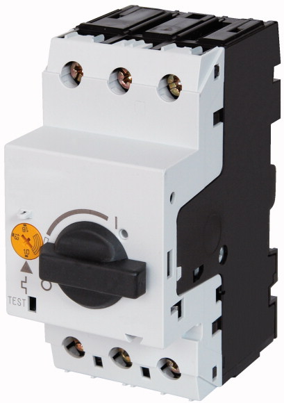
Short-circuit protective breaker, Iu 6.3 A, Irm 97.7 A, Screw terminals, Also suitable for motors with efficiency class IE3.Motor-protective circuit-breaker according to IEC/EN60947, 3 pole size PKM0, with non-delayed short-circuit release, screw and snap fitting, with screw terminal, cap installation dimension 45mm, rated operating voltage Ue 690V, degree of protection IP20, finger proof according to VDE 0106 T. 100, accessories: auxiliary contact, voltage release, contact module, clip plate
Short-circuit protective breaker, Iu 6.3 A, Irm 97.7 A, Screw terminals, Also suitable for motors with efficiency class IE3.
Motor-protective circuit-breaker according to IEC/EN60947, 3 pole size PKM0, with non-delayed short-circuit release, screw and snap fitting, with screw terminal, cap installation dimension 45mm, rated operating voltage Ue 690V, degree of protection IP20, finger proof according to VDE 0106 T. 100, accessories: auxiliary contact, voltage release, contact module, clip plate
| Product range | PKM0 motor protective circuit-breakers up to 32 A | |||||||||||||||||
| Basic function | Short-circuit protective device only | |||||||||||||||||
| Notes | ||||||||||||||||||
| Connection technique | Also suitable for motors with efficiency class IE3. IE3-ready devices are identified by the logo on their packaging. |
|||||||||||||||||
| Contact sequence | Screw terminals | |||||||||||||||||
| AC-3 >220 V 230 V 240 V [P] |
||||||||||||||||||
| AC-3 >380 V 400 V 415 V [P] |
||||||||||||||||||
| AC-3 >440 V [P] |
1.1 kW | |||||||||||||||||
| AC-3 >500 V [P] |
2.2 kW | |||||||||||||||||
| AC-3 >660 V 690 V [P] |
3 kW | |||||||||||||||||
| Rated uninterrupted current [Iu] | 3 kW | |||||||||||||||||
| short-circuit release >max. [Irm ] |
4 kW | |||||||||||||||||
| Notes | 6.3 A | |||||||||||||||||
| Notes | ||||||||||||||||||
| Standards | 97.7 A | |||||||||||||||||
| Climatic proofing | An appropriate overload relay must be fitted to protect motors against overload. Can be snapped on to IEC/EN 60715 top-hat rail with 7.5 or 15 mm height. Refer to catalog CA034001DE for the allocation of short circuit protection and contactor |
|||||||||||||||||
| Ambient temperature >Storage |
|
|||||||||||||||||
| Ambient temperature >Open |
||||||||||||||||||
| Ambient temperature >Enclosed |
IEC/EN 60947, VDE 0660 | |||||||||||||||||
| Mounting position | Damp heat, constant, to IEC 60068-2-78 Damp heat, cyclic, to IEC 60068-2-30 |
|||||||||||||||||
| Direction of incoming supply | - 40 - 80 °C | |||||||||||||||||
| Degree of protection >Device |
-25 - +55 °C | |||||||||||||||||
| Degree of protection >Terminations |
- 25 - 40 °C | |||||||||||||||||
| Protection against direct contact when actuated from front (EN 50274) | ||||||||||||||||||
| Mechanical shock resistance half-sinusoidal shock 10 ms to IEC 60068-2-27 | as required | |||||||||||||||||
| Altitude | IP20 | |||||||||||||||||
| Terminal capacity main cable >Screw terminals >Solid |
IP00 | |||||||||||||||||
| Terminal capacity main cable >Screw terminals >Flexible with ferrule to DIN 46228 |
Finger and back-of-hand proof | |||||||||||||||||
| Terminal capacity main cable >Screw terminals >Solid or stranded |
25 g | |||||||||||||||||
| Terminal capacity main cable >Screw terminals >Stripping length |
Max. 2000 m | |||||||||||||||||
| Specified tightening torque for terminal screws >Main cable |
1 x (1 - 6) 2 x (1 - 6) mm2 |
|||||||||||||||||
| Specified tightening torque for terminal screws >Control circuit cables |
1 x (1 - 6) 2 x (1 - 6) mm2 |
|||||||||||||||||
| Rated impulse withstand voltage [Uimp] | 18 - 10 AWG | |||||||||||||||||
| Overvoltage category/pollution degree | 10 mm | |||||||||||||||||
| Rated operational voltage [Ue ] | 1.7 Nm | |||||||||||||||||
| Rated uninterrupted current = rated operational current [Iu = Ie ] | 1 Nm | |||||||||||||||||
| Rated frequency [f] | ||||||||||||||||||
| Current heat loss (3 pole at operating temperature) | 6000 V AC | |||||||||||||||||
| Impedance per pole | III/3 | |||||||||||||||||
| Lifespan, mechanical [Operations] | 690 V AC | |||||||||||||||||
| Lifespan, electrical (AC-3 at 400 V) >Lifespan, electrical [Operations] |
6.3 A | |||||||||||||||||
| Max. operating frequency | 40 - 60 Hz | |||||||||||||||||
| Motor switching capacity >AC-3 (up to 690V) |
5.68 W | |||||||||||||||||
| Motor switching capacity >DC-5 (up to 250V) |
46 mΩ | |||||||||||||||||
| Temperature compensation >to IEC/EN 60947, VDE 0660 |
0.1 x 10⁶ | |||||||||||||||||
| Temperature compensation >Operating range |
0.1 x 10⁶ | |||||||||||||||||
| Temperature compensation residual error for T > 40 °C | 40 Ops/h | |||||||||||||||||
| short-circuit release | 6.3 A | |||||||||||||||||
| Short-circuit release tolerance | 6.3 (3 contacts in series) A | |||||||||||||||||
| Rated operational current for specified heat dissipation [In] | ||||||||||||||||||
| Heat dissipation per pole, current-dependent [Pvid] | - 5…40 °C | |||||||||||||||||
| Equipment heat dissipation, current-dependent [Pvid] | - 25…55 °C | |||||||||||||||||
| Static heat dissipation, non-current-dependent [Pvs] | ≦ 0.25 %/K | |||||||||||||||||
| Heat dissipation capacity [Pdiss] | Basic device, fixed: 15.5 x Iu | |||||||||||||||||
| Operating ambient temperature min. | ± 20% | |||||||||||||||||
| Operating ambient temperature max. | ||||||||||||||||||
| 10.2 Strength of materials and parts >10.2.2 Corrosion resistance |
6.3 A | |||||||||||||||||
| 10.2 Strength of materials and parts >10.2.3.1 Verification of thermal stability of enclosures |
1.89 W | |||||||||||||||||
| 10.2 Strength of materials and parts >10.2.3.2 Verification of resistance of insulating materials to normal heat |
5.68 W | |||||||||||||||||
| 10.2 Strength of materials and parts >10.2.3.3 Verification of resistance of insulating materials to abnormal heat and fire due to internal electric effects |
0 W | |||||||||||||||||
| 10.2 Strength of materials and parts >10.2.4 Resistance to ultra-violet (UV) radiation |
0 W | |||||||||||||||||
| 10.2 Strength of materials and parts >10.2.5 Lifting |
-25 °C | |||||||||||||||||
| 10.2 Strength of materials and parts >10.2.6 Mechanical impact |
+55 °C | |||||||||||||||||
| 10.2 Strength of materials and parts >10.2.7 Inscriptions |
||||||||||||||||||
| 10.3 Degree of protection of ASSEMBLIES | Meets the product standard´s requirements. | |||||||||||||||||
| 10.4 Clearances and creepage distances | Meets the product standard´s requirements. | |||||||||||||||||
| 10.5 Protection against electric shock | Meets the product standard´s requirements. | |||||||||||||||||
| 10.6 Incorporation of switching devices and components | Meets the product standard´s requirements. | |||||||||||||||||
| 10.7 Internal electrical circuits and connections | Meets the product standard´s requirements. | |||||||||||||||||
| 10.8 Connections for external conductors | Does not apply, since the entire switchgear needs to be evaluated. | |||||||||||||||||
| 10.9 Insulation properties >10.9.2 Power-frequency electric strength |
Does not apply, since the entire switchgear needs to be evaluated. | |||||||||||||||||
| 10.9 Insulation properties >10.9.3 Impulse withstand voltage |
Meets the product standard´s requirements. | |||||||||||||||||
| 10.9 Insulation properties >10.9.4 Testing of enclosures made of insulating material |
Does not apply, since the entire switchgear needs to be evaluated. | |||||||||||||||||
| 10.10 Temperature rise | Meets the product standard´s requirements. | |||||||||||||||||
| 10.11 Short-circuit rating | Does not apply, since the entire switchgear needs to be evaluated. | |||||||||||||||||
| 10.12 Electromagnetic compatibility | Does not apply, since the entire switchgear needs to be evaluated. | |||||||||||||||||
| 10.13 Mechanical function | Is the panel builder´s responsibility. | |||||||||||||||||
| Overload release current setting | Is the panel builder´s responsibility. | |||||||||||||||||
| Adjustment range undelayed short-circuit release | Is the panel builder´s responsibility. | |||||||||||||||||
| With thermal protection | Is the panel builder´s responsibility. | |||||||||||||||||
| Phase failure sensitive | Is the panel builder´s responsibility. | |||||||||||||||||
| Switch off technique | The panel builder is responsible for the temperature rise calculation. Eaton will provide heat dissipation data for the devices. | |||||||||||||||||
| Rated operating voltage | Is the panel builder´s responsibility. The specifications for the switchgear must be observed. | |||||||||||||||||
| Rated permanent current Iu | Is the panel builder´s responsibility. The specifications for the switchgear must be observed. | |||||||||||||||||
| Rated operation power at AC-3, 230 V | The device meets the requirements, provided the information in the instruction leaflet (IL) is observed. | |||||||||||||||||
| Rated operation power at AC-3, 400 V | ||||||||||||||||||
| Type of electrical connection of main circuit | ||||||||||||||||||
| Type of control element | 0 - 0 A | |||||||||||||||||
| Device construction | 98 - 98 A | |||||||||||||||||
| With integrated auxiliary switch | No | |||||||||||||||||
| With integrated under voltage release | No | |||||||||||||||||
| Number of poles | Magnetic | |||||||||||||||||
| Rated short-circuit breaking capacity lcu at 400 V, AC | 690 - 690 V | |||||||||||||||||
| Degree of protection (IP) | 6.3 A | |||||||||||||||||
| Height | 1.1 kW | |||||||||||||||||
| Width | 2.2 kW | |||||||||||||||||
| Depth | Screw connection | |||||||||||||||||
| Specially designed for North America | Turn button | |||||||||||||||||
| Accessories | Built-in device fixed built-in technique | |||||||||||||||||
| Characteristic curve | No | |||||||||||||||||
| Characteristic curve | No |
All of our products ensure maximum reliability even in challenging working conditions and help your business operations run smoothly. The products we offer in industrial automation, energy management, cabling solutions, and many other areas adapt flexibly to the needs of different sectors.
Additionally, our products are manufactured using only high-quality materials and comply with international standards. Through the solutions we provide, we enable our customers to increase operational efficiency and optimize costs. Our company closely follows technological advancements and continuously offers innovative products to help our customers gain a competitive advantage.
On each of our product pages, you can find comprehensive information about technical details, areas of use, and product features. You can explore all the products you need to strengthen your industrial processes on our website and enjoy a seamless purchasing experience.
Similar Products


Can't find the product you're looking for?
LET US HELP YOU
Can't Find the Product You're Looking For? Let Us Know, and We'll Source It for You!
Are you searching for products not listed on our website or out of stock? Let us know your requirements, and our expert team will contact you as soon as possible to find the most suitable solution for you.