| Measured values | CH4, CO, CO2, Corg, HCl, H2O, NH3, NO, NO2, N2O, O2, SO2 |
| Performance-tested measurands | CH4, CO, CO2, Corg, HCl, H2O, NH3, NO, NO2, N2O, O2, SO2 |
| Maximum number of measurands | 12 |
| Measurement principles | Interference filter correlation, Gas filter correlation |
| Length of measuring path | | | 8.48 m |
|
| Gas flow rate | | | 200 l/h ... 400 l/h |
|
| Measuring ranges | | | CH4 | 0 ... 70 ppm / 0 ... 700 ppm | | SO2 | 0 ... 26 ppm / 0 ... 875 ppm | | CO | 0 ... 60 ppm / 0 ... 8,000 ppm | | CO2 | 0 ... 25 Vol.-% / 0 ... 50 Vol.-% | | Corg | 0 ... 15 mg/m³ / 0 ... 10,000 mg/m³ | | HCl | 0 ... 9 ppm / 0 ... 1,840 ppm | | H2O | 0 ... 40 Vol.-% | | NH3 | 0 ... 15 ppm / 0 ... 650 ppm | | NO | 0 ... 110 ppm / 0 ... 1,865 ppm | | NO2 | 0 ... 25 ppm / 0 ... 240 ppm | | N2O | 0 ... 50 ppm / 0 ... 1,015 ppm | | O2 | 0 ... 25 Vol.-% |
|
| Certified measuring ranges | | | CH4 | 0 ... 50 mg/m³ / 0 ... 500 mg/m³ | | CO | 0 ... 75 mg/m³ / 0 ... 10,000 mg/m³ | | CO2 | 0 ... 25 Vol.-% | | Corg | 0 ... 15 mg/m³ / 0 ... 50 mg/m³ / 0 ... 150 mg/m³ / 0 ... 500 mg/m³ | | HCl | 0 ... 15 mg/m³ / 0 ... 3,000 mg/m³ | | H2O | 0 ... 40 Vol.-% | | NH3 | 0 ... 10 mg/m³ / 0 ... 500 mg/m³ | | NO | 0 ... 150 mg/m³ / 0 ... 2,500 mg/m³ | | NO2 | 0 ... 50 mg/m³ / 0 ... 500 mg/m³ | | N2O | 0 ... 100 mg/m³ / 0 ... 2,000 mg/m³ | | O2 | 0 ... 25 Vol.-% | | SO2 | 0 ... 75 mg/m³ / 0 ... 2,500 mg/m³ |
|
| Response time (t90) | ≤ 200 s |
| Accuracy | | | ≤ 2 %
Relative to measuring range end value |
|
| Sensitivity drift | | | ≤ 3 %: within the maintenance interval, relative to measuring range full scale |
|
| Zero point drift | | | < 3 %: of the measuring range full scale value per maintenance interval |
|
| Reference point drift | | | < 3 %: of the measuring range full scale value per maintenance interval |
|
| Detection limit | | | ≤ 2 %: relative to measuring range end value | | TOC measurement | 0.05 mg/m³ |
|
| Reproducibility | | | ≤ 3.3 %: relative to measuring range end value | | O2 measurement | ≤ 0.2 Vol.-% |
|
| Uncertainty of measurement | | | ≤ 2 %
Of measuring range full scale |
|
| Process temperature | | | ≤ +1,300 °C |
|
| Sample gas temperature | | | Inlet analyzer system | ≤ +200 °C |
|
| Process pressure | | | 850 hPa ... 1,100 hPa |
|
| Process gas humidity | | | ≤ 40 Vol.-% |
|
| Ambient temperature | | | –20 °C ... +50 °C |
|
| Storage temperature | | | –20 °C ... +55 °C |
|
| Ambient pressure | | | 850 hPa ... 1,100 hPa |
|
| Ambient humidity | | | ≤ 90 %
Relative humidity; non-condensing |
|
| Ex-approvals | | | ATEX | II 3G Ex dc ec ic [ic] mc nC pzc IIC T3 Gc
Analyzer cabinet | | II 3G Ex ec IIC T3 Gc
Gas sampling unit | | II 2G Ex 60079-30-1 eb IIC T3 Gb
Sample gas line |
|
| Electrical safety | CE |
|
| Analog outputs | 0/4 ... 22 mA, 500 Ω
Number depends on system configuration |
| Analog inputs | 0/4 ... 22 mA, 100 Ω
Number depends on system configuration; electrically isolated |
| Digital outputs | 48 V AC, 0.5 A, 35 W / 48 V DC, 0.5 A, 24 W
Number depends on system configuration; electrically isolated |
| Digital inputs | 3.9 V, 4.5 mA, 0.55 W
Number depends on system configuration |
Modbus | ✔ , ✔ | | Type of fieldbus integration | TCP | | RTU RS-485 |
|
|
|
| Ethernet | ✔ | | Function | Connection to SOPAS ET software or OPC server |
|
| Indication | | | LC display | | Status LEDs: “Power,” “Failure,” and “Maintenance request” |
|
| Input | Touchscreen |
| Operation | Via LC display or SOPAS ET software, multiple operating levels, password-protected |
| Menu languages | German, English |
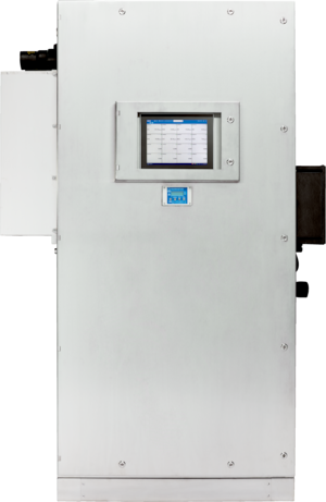
| Dimensions (W x H x D) | | | Analyzer cabinet | 1,448 mm x 2,160 mm x 652 mm (for details see dimensional drawings) |
|
| Weight | | | Analyzer cabinet | Approx. 400 kg |
|
| Material in contact with media | Stainless steel 304, Option: GFRP, painted sheet steel |
| Energy supply | | | Voltage | 115 V AC, ± 10 % | | 230 V AC, ± 10 % | | Frequency | 50 Hz / 60 Hz | | Power consumption | Analyzer: ≤ 1,000 VA | | Sample gas line, heated: ≤ 95 VA/m | | Gas sampling unit: ≤ 450 VA | | Heated probe tube: ≤ 200 VA ... ≤ 600 VA |
|
| Auxiliaries | | | Instrument air (zero gas quality) | ≤ 350 l/h
6 ... 7 bar; particle size max. 1 µm; oil content max. 0.1 mg/m³; pressure condensation point max. –40 °C, purity class 2 (ISO 8573) | | Instrument air (propellant air for ejector) | ≤ 1,300 l/h
5 ... 7 bar; particle size max. 5 µm; oil content max. 1 mg/m³; pressure condensation point max. -+3 °C, purity class 3 (ISO 8573) | | Reference gas | ≤ 350 l/h
Max. 4 bar; the reference gas must comply with the requirements of the applicable standards and guidelines | | Instrument air Ex p (flushing unit) | Max. 4.5 barg (system-side regulation), specification according to ISO 8573-1:5-3-3, particle size: max. 40 μm (Class 5), dew point: ≤ –20 °C (Class 3), oil content: ≤ 1 mg/m3 (Class 3), air volume: 39,100 l/h |
|
| Sample gas connections | | | Sample gas inlet | Clamping ring fitting for 6 mm pipes |
|
| Auxiliary gas connections | | | Propellant air for ejector | DN 6/8 | | Reference gas | Clamping ring fitting for 6 mm pipes | | Exhaust gas outlet | DN 8/10 |
|
| Corrective functions | Drift correction and optical monitoring function via adjustment cell |
| Test functions | Automatic check cycle for zero and span point |
| System components | Gas sampling unit Sample gas line Analyzer cabinet |