Schmersal : SRB-E-602EM-CC-103055591
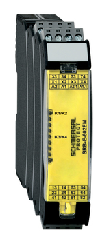
SRB-E-602EM-CC
SRB-E-602EM-CC-103055591
Plug-in spring-cage terminal blocks with codingExpander module for contact expansion1 x 6 safety contacts, STOP 0 or 2 x 3 safety contacts, STOP 02 Signalling contacts
- Plug-in spring-cage terminal blocks with coding
- Expander module for contact expansion
- 1 x 6 safety contacts, STOP 0 or 2 x 3 safety contacts, STOP 0
- 2 Signalling contacts
Ordering data
| Product type description | SRB-E-602EM-CC |
| Article number (order number) | 103055591 |
| EAN (European Article Number) | 4030661646756 |
Approvals - Standards
| cULus CCC |
General data
| Standards | EN IEC 62061 EN ISO 13849-1 EN IEC 60947-5-1 EN IEC 60947-5-3 EN IEC 60947-5-5 EN IEC 61508 EN IEC 60204-1 EN IEC 60947-1 |
| Climatic stress | EN 60068-2-78 |
| Housing material | Glass-fibre reinforced thermoplastic, ventilated |
General data - Features
| Wire breakage detection | Yes |
| Removable Terminals | Yes |
| Feedback circuit | Yes |
| Automatic reset function | Yes |
| Earth connection detection | Yes |
| Integral system diagnostics, status | Yes |
| Number of auxiliary contacts | 2 |
| Number of LEDs | 2 |
| Number of normally closed (NC) | 2 |
| Number of safety contacts | 6 |
| Safety classification |
| Standards | EN ISO 13849-1 EN IEC 61508 |
| Stop-Category | 0 |
| Safety classification - Relay outputs |
| Performance Level, stop 0, up to | e |
| Category, Stop 0 | 4 |
| Diagnostic Coverage (DC) Level, Stop 0 | ≥ 99 % |
| PFH value, Stop 0 | 2.00 x 10⁻⁸ /h |
| Safety Integrity Level (SIL), Stop 0, suitable for applications in | 3 |
| Mission time | 20 Year(s) |
| Common Cause Failure (CCF), minimum | 65 |
Mechanical data
| Mechanical life, minimum | 10,000,000 Operations |
| Mounting | Snaps onto standard DIN rail to EN 60715 |
Mechanical data - Connection technique
| Terminal designations | EN 60947-1 |
| Termination | Cage clamp, plug-in rigid or flexible |
| Cable section, minimum | 0.25 mm² |
| Cable section, maximum | 1.5 mm² |
| Tightening torque of Clips | 0.5 Nm |
Mechanical data - Dimensions
| Width | 22.5 mm |
| Height | 98 mm |
| Depth | 115 mm |
Ambient conditions
| Degree of protection of the enclosure | IP40 |
| Degree of protection of the mounting space | IP54 |
| Degree of protection of clips or terminals | IP20 |
| Ambient temperature | -25 ... +60 °C |
| Storage and transport temperature | -40 ... +85 °C |
| Resistance to vibrations | 10...55 Hz, Amplitude 0.35 mm, ± 15 % |
| Restistance to shock | 10 g / 11 ms |
Ambient conditions - Insulation values
| Rated impulse withstand voltage Uimp | 4 kV |
| Overvoltage category | III |
| Degree of pollution | 2 |
Electrical data
| Frequency range | 50 Hz 60 Hz |
| Operating voltage | 24 VAC -15 % / +10 % |
| Ripple voltage | 10 % |
| Rated operating voltage | 24 VAC |
| Rated operating voltage | 24 VDC |
| Rated AC voltage for controls, 50 Hz, minimum | 20.4 VAC |
| Rated control voltage at AC 50 Hz, maximum | 26.4 VAC |
| Rated AC voltage for controls, 60 Hz, minimum | 20.4 VAC |
| Rated control voltage at AC 60 Hz, maximum | 26.4 VAC |
| Rated AC voltage for controls at DC minimum | 20.4 VDC |
| Rated control voltage at DC, maximum | 28.8 VDC |
| Electrical power consumption | 2.9 W |
| Electrical power consumption | 4.9 VA |
| Contact resistance, maximum | 0.1 Ω |
| Note (Contact resistance) | in new state |
| Drop-out delay, maximum | 35 ms |
| Pull-in delay at automatic start, maximum, typically | 20 ms |
| Material of the contacts, electrical | Ag-Ni, self-cleaning, positive drive |
Electrical data - Safe relay outputs
| Voltage, Utilisation category AC-15 | 230 VAC |
| Current, Utilisation category AC-15 | 4 A |
| Voltage, Utilisation category DC-13 | 24 VDC |
| Current, Utilisation category DC-13 | 4 A |
| Switching capacity, minimum | 10 VDC |
| Switching capacity, minimum | 10 mA |
| Switching capacity, maximum | 250 VAC |
| Switching capacity, maximum | 6 A |
Electrical data - Digital inputs
| Conduction resistance, maximum | 40 Ω |
Electrical data - Relay outputs (auxiliary contacts)
| Switching capacity, maximum | 24 VDC |
| Switching capacity, maximum | 2 A |
Electrical data - Electromagnetic compatibility (EMC)
| EMC rating | EMC-Directive |
Status indication
| Indicated operating states | Position relay K3/K4 Position relay K1/K2 |
Note
| Note (General) | Inductive loads (e.g. contactors, relays, etc.) are to be suppressed by means of a suitable circuit. |
All of our products ensure maximum reliability even in challenging working conditions and help your business operations run smoothly. The products we offer in industrial automation, energy management, cabling solutions, and many other areas adapt flexibly to the needs of different sectors.
Additionally, our products are manufactured using only high-quality materials and comply with international standards. Through the solutions we provide, we enable our customers to increase operational efficiency and optimize costs. Our company closely follows technological advancements and continuously offers innovative products to help our customers gain a competitive advantage.
On each of our product pages, you can find comprehensive information about technical details, areas of use, and product features. You can explore all the products you need to strengthen your industrial processes on our website and enjoy a seamless purchasing experience.
Similar Products


Can't find the product you're looking for?
LET US HELP YOU
Can't Find the Product You're Looking For? Let Us Know, and We'll Source It for You!
Are you searching for products not listed on our website or out of stock? Let us know your requirements, and our expert team will contact you as soon as possible to find the most suitable solution for you.