Schmersal : RSS 36-SD-R-ST-101217290
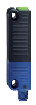
RSS 36-SD-R-ST
RSS 36-SD-R-ST-101217290
Universal coding with RFID technology1 x connector socket M12, 8-poleActuation from sideMax. 31 sensors can be wired in series.serial diagnostic outputThermoplastic enclosureRFID-technology for needs-based protection against tamperingMisaligned actuation possible27 mm x 108.2 mm x 35 mmHigh repeat accuracy of the switching points2 short-circuit proof PNP safety outputsIntegral cross-short, wire-breakage and external voltage monitoring of the safety cables up to the control cabinet
- Universal coding with RFID technology
- 1 x connector socket M12, 8-pole
- Actuation from side
- Max. 31 sensors can be wired in series.
- serial diagnostic output
- Thermoplastic enclosure
- RFID-technology for needs-based protection against tampering
- Misaligned actuation possible
- 27 mm x 108.2 mm x 35 mm
- High repeat accuracy of the switching points
- 2 short-circuit proof PNP safety outputs
- Integral cross-short, wire-breakage and external voltage monitoring of the safety cables up to the control cabinet
Ordering data
| Product type description | RSS 36-SD-R-ST |
| Article number (order number) | 101217290 |
| EAN (European Article Number) | 4030661413419 |
| eCl@ss number, version 12.0 | 27-27-46-01 |
| eCl@ss number, version 11.0 | 27-27-24-03 |
| eCl@ss number, version 9.0 | 27-27-24-03 |
| ETIM number, version 7.0 | EC001829 |
| ETIM number, version 6.0 | EC001829 |
Approvals - Standards
| TÜV cULus ECOLAB FCC IC UKCA ANATEL |
General data
| Standards | EN ISO 13849-1 EN IEC 60947-5-3 EN IEC 61508 |
| Coding | Universal coding |
| Coding level according to EN ISO 14119 | Low |
| Working principle | RFID |
| Frequency band RFID | 125 kHz |
| Transmitter output RFID, maximum | -6 dB/m |
| Housing construction form | Block |
| Installation conditions (mechanical) | not flush |
| Sensor topology | Sensor for series wiring |
| Housing material | Glass-fibre, reinforced thermoplastic |
| Reaction time, maximum | 100 ms |
| Duration of risk, maximum | 200 ms |
| Reaction time, switching off safety outputs via actuator, maximum | 100 ms |
| Reaction time, switching off safety outputs via safety inputs, maximum | 0.5 ms |
| Gross weight | 100 g |
General data - Features
| Serial diagnostics | Yes |
| Latching | Yes |
| Short circuit detection | Yes |
| Cross-circuit detection | Yes |
| Series-wiring | Yes |
| Safety functions | Yes |
| Cascadable | Yes |
| Integral system diagnostics, status | Yes |
| Number of LEDs | 3 |
| Number of semi-conductor outputs with signaling function | 1 |
| Number of fail-safe digital outputs | 2 |
| Number of series-wiring of sensors | 31 |
| Safety classification |
| Standards | EN ISO 13849-1 EN IEC 61508 |
| Performance Level, up to | e |
| Category | 4 |
| PFH value | 2.70 x 10⁻¹⁰ /h |
| PFD value | 2.10 x 10⁻⁵ |
| Safety Integrity Level (SIL), suitable for applications in | 3 |
| Mission time | 20 Year(s) |
Mechanical data
| Actuating panels | lateral |
| Active area | lateral |
| Mechanical life, minimum | 1,000,000 Operations |
| Note (Mechanical life) | Actuating speed Operations for door weights ≤ 5 kg |
| Latching force, approx. | 18 N |
| Mounting | A screw length of 25 mm is sufficient for sensor mounting and for side mounting of the actuators. 30 mm long screws are recommended when the actuator is mounted upright and/or when the sealing discs are used. |
| Type of the fixing screws | 2x M4 (cylinder head screws with washers DIN 125A / form A) |
| Tightening torque of the fixing screws, minimum | 2.2 Nm |
| Tightening torque of the fixing screws, maximum | 2.5 Nm |
Mechanical data - Switching distances according EN IEC 60947-5-3
| Switch distance, typical | 12 mm |
| Assured switching distance "ON" Sao | 10 mm |
| Assured switching distance "OFF" Sar | 20 mm |
| Hysteresis (Switching distance), maximum | 2 mm |
| Repeat accuracy R | 0.5 mm |
| Note (Repeat accuracy R) | Axial offset: The long side allows for a maximum height misalignment (x) of sensor and actuator of 8 mm (e.g. mounting tolerance or due to guard door sagging). The axial misalignment (y) is max. ± 18 mm (see figure: Operating principle).Minimum clearance between two sensor systems 100 mm. |
Mechanical data - Connection technique
| Note (length of the sensor chain) | Cable length and cross-section change the voltage drop dependiing on the output current |
| Note (series-wiring) | Unlimited number of devices, oberserve external line fusing, max. 31 devices in case of serial diagnostic SD |
| Termination | Connector M12, 8-pole |
Mechanical data - Dimensions
| Length of sensor | 22 mm |
| Width of sensor | 106.3 mm |
| Height of sensor | 25 mm |
Ambient conditions
| Degree of protection | IP65 IP67 IP69 |
| Ambient temperature | -28 ... +70 °C |
| Storage and transport temperature | -28 ... +85 °C |
| Relative humidity, maximum | 93 % |
| Note (Relative humidity) | non-condensing non-icing |
| Resistance to vibrations | 10 … 55 Hz, amplitude 1 mm |
| Restistance to shock | 30 g / 11 ms |
| Protection class | III |
| Permissible installation altitude above sea level, maximum | 2,000 m |
Ambient conditions - Insulation values
| Rated insulation voltage Ui | 32 VDC |
| Rated impulse withstand voltage Uimp | 0.8 kV |
| Overvoltage category | III |
| Degree of pollution | 3 |
Electrical data
| Operating voltage | 24 VDC -15 % / +10 % (stabilised PELV power supply) |
| Operating current, minimum | 0.5 mA |
| No-load supply current I0, typical | 35 mA |
| Rated operating voltage | 24 VDC |
| Operating current | 600 mA |
| Required rated short-circuit current | 100 A |
| Time to readiness, maximum | 2,000 ms |
| Switching frequency, maximum | 1 Hz |
| Electrical fuse rating, maximum | 2 A |
Electrical data - Safety digital inputs
| Designation, Safety inputs | X1 and X2 |
| Current consumption of the safety inputs | 5 mA |
| Test pulse duration, maximum | 1 ms |
| Test pulse interval, minimum | 100 ms |
| Classification ZVEI CB24I, Sink | C1 |
| Classification ZVEI CB24I, Source | C1 C2 C3 |
Electrical data - Safety digital outputs
| Designation, Safety outputs | Y1 and Y2 |
| Rated operating current (safety outputs) | 250 mA |
| Output current, (fail-safe output), maximum | 0.25 A |
| Design of control elements | short-circuit proof, p-type |
| Voltage drop Ud, maximum | 1 V |
| Leakage current Ir, maximum | 0.5 mA |
| Voltage, Utilisation category DC-12 | 24 VDC |
| Current, Utilisation category DC-12 | 0.25 A |
| Voltage, Utilisation category DC-13 | 24 VDC |
| Current, Utilisation category DC-13 | 0.25 A |
| Test pulse interval, typical | 1000 ms |
| Test pulse duration, maximum | 0.3 ms |
| Classification ZVEI CB24I, Source | C2 |
| Classification ZVEI CB24I, Sink | C1 C2 |
Electrical data - Serial diagnostic SD
| Designation, Serial diagnostic SD | OUT |
| Operation current | 150 mA |
| Design of control elements | short-circuit proof, p-type |
| Wiring capacitance | 50 nF |
Electrical data - Electromagnetic compatibility (EMC)
| Interfering radiation | IEC 61000-6-4 |
Status indication
| Note (LED switching conditions display) | LED yellow: Operating condition LED green: Supply voltage LED red: Fault |
Pin assignment
| PIN 1 | 1A1 Ue: (1) |
| PIN 2 | X1 Safety input 1 |
| PIN 3 | A2 GND Blue |
| PIN 4 | Y1 Safety output 1 Black |
| PIN 5 | serial diagnostic output OUT Grey |
| PIN 6 | X2 Safety input 2 violet |
| PIN 7 | Y2 Safety output 2 red |
| PIN 8 | IN serial diagnostic input Pink |
Scope of delivery
| Scope of delivery | Actuator must be ordered separately. |
Accessory
| Recommendation (actuator) | RST 36-1 RST 36-1-R |
| Recommended safety switchgear | PROTECT PSC1 SRB-E-301ST SRB-E-201LC |
Note
| Note (General) | Evaluation requirements: dual-channel safety input, suitable for p-type sensors with NO function. The safety-monitoring module must tolerate internal functional tests of the sensors with cyclic switch-off of the sensor outputs for max. 0.5 ms. Short-circuit recognition by the evaluation is not necessary. |
All of our products ensure maximum reliability even in challenging working conditions and help your business operations run smoothly. The products we offer in industrial automation, energy management, cabling solutions, and many other areas adapt flexibly to the needs of different sectors.
Additionally, our products are manufactured using only high-quality materials and comply with international standards. Through the solutions we provide, we enable our customers to increase operational efficiency and optimize costs. Our company closely follows technological advancements and continuously offers innovative products to help our customers gain a competitive advantage.
On each of our product pages, you can find comprehensive information about technical details, areas of use, and product features. You can explore all the products you need to strengthen your industrial processes on our website and enjoy a seamless purchasing experience.
Similar Products
Can't find the product you're looking for?
LET US HELP YOU
Can't Find the Product You're Looking For? Let Us Know, and We'll Source It for You!
Are you searching for products not listed on our website or out of stock? Let us know your requirements, and our expert team will contact you as soon as possible to find the most suitable solution for you.

