Schmersal : MZM 100 ST2-1P2P-A-DU-103047122
MZM 100 ST2-1P2P-A-DU
MZM 100 ST2-1P2P-A-DU-103047122
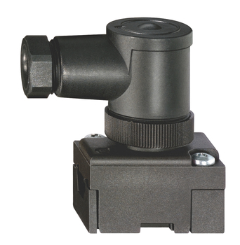
Guard locking monitoredPower to lockConnector M12, 8-poleAutomatic latchingSolenoid interlocks with innovating and unique operating principle40 mm x 179 mm x 40 mmElectronic contact-free, coded systemThermoplastic enclosureMax. length of the sensor chain 200 m3 LEDs to show operating conditionsSensor technology permits an offset between actuator and interlock of ± 5 mm vertically and ± 3 mm horizontallyIntelligent diagnosisSelf-monitoring series-wiring
- Guard locking monitored
- Power to lock
- Connector M12, 8-pole
- Automatic latching
- Solenoid interlocks with innovating and unique operating principle
- 40 mm x 179 mm x 40 mm
- Electronic contact-free, coded system
- Thermoplastic enclosure
- Max. length of the sensor chain 200 m
- 3 LEDs to show operating conditions
- Sensor technology permits an offset between actuator and interlock of ± 5 mm vertically and ± 3 mm horizontally
- Intelligent diagnosis
- Self-monitoring series-wiring
Ordering data
| Note (Delivery capacity) | Not available! |
| Product type description | MZM 100 ST2-1P2P-A-DU |
| Article number (order number) | 103047122 |
| EAN (European Article Number) | 4030661616278 |
| eCl@ss number, version 12.0 | 27-27-26-03 |
| eCl@ss number, version 11.0 | 27-27-26-03 |
| eCl@ss number, version 9.0 | 27-27-26-03 |
| ETIM number, version 7.0 | EC002593 |
| ETIM number, version 6.0 | EC002593 |
Approvals - Standards
| TÜV cULus UKCA |
General data
| Standards | EN ISO 13849-1 EN ISO 14119 EN IEC 60947-5-3 EN IEC 61508 |
| Coding | Universal coding |
| Coding level according to EN ISO 14119 | Low |
| Working principle | inductive |
| Housing material | Plastic, glass-fibre reinforced thermoplastic, self-extinguishing |
| Reaction time, maximum | 150 ms |
| Duration of risk, maximum | 150 ms |
| Gross weight | 703 g |
General data - Features
| Power to lock | Yes |
| Solenoid interlock monitored | Yes |
| Short circuit detection | Yes |
| Cross-circuit detection | Yes |
| Series-wiring | Yes |
| Safety functions | Yes |
| Integral system diagnostics, status | Yes |
| Number of safety contacts | 2 |
| Safety classification |
| Standards | EN ISO 13849-1 EN IEC 61508 |
Safety classification - Interlocking function
| Performance Level, up to | e |
| Category | 4 |
| PFH value | 3.54 x 10⁻⁹ /h |
| Safety Integrity Level (SIL), suitable for applications in | 3 |
| Mission time | 20 Year(s) |
Mechanical data
| Mechanical life, minimum | 1,000,000 Operations |
| Note (Mechanical life) | Actuating speed ≤ 0.5 m/s Operations for door weights ≤ 5 kg |
| Holding force, typically | 750 N |
| Holding force, guaranteed | 500 N |
| Type of the fixing screws | 2x M6 |
| Tightening torque of the fixing screws | 8 Nm |
Mechanical data - Switching distances according EN IEC 60947-5-3
| Assured switching distance "ON" Sao | 0 mm |
| Assured switching distance "OFF" Sar | 1 mm |
Mechanical data - Connection technique
| Length of sensor chain, maximum | 200 m |
| Note (length of the sensor chain) | Cable length and cross-section change the voltage drop dependiing on the output current |
| Note (series-wiring) | Unlimited number of devices, oberserve external line fusing, max. 31 devices in case of serial diagnostic SD |
| Termination | Connector M12, 8-pole |
Mechanical data - Dimensions
| Length of sensor | 40 mm |
| Width of sensor | 40 mm |
| Height of sensor | 177.5 mm |
Ambient conditions
| Degree of protection | IP65 IP67 |
| Ambient temperature | -25 ... +55 °C |
| Storage and transport temperature | -25 ... +70 °C |
| Relative humidity, minimum | 30 % |
| Relative humidity, maximum | 95 % |
| Note (Relative humidity) | non-condensing non-icing |
| Resistance to vibrations | 10 … 150 Hz, amplitude 0.35 mm / 5 g |
| Restistance to shock | 30 g / 11 ms |
| Protection class | III |
| Permissible installation altitude above sea level, maximum | 2,000 m |
Ambient conditions - Insulation values
| Rated insulation voltage Ui | 32 VDC |
| Rated impulse withstand voltage Uimp | 0.8 kV |
| Overvoltage category | III |
| Degree of pollution | 3 |
Electrical data
| Operating voltage | 24 VDC -15 % / +10 % (stabilised PELV power supply) |
| No-load supply current I0, typical | 100 mA |
| Current consumption with magnet ON, average | 350 mA |
| Current consumption with magnet ON, peak | 550 mA / 10 ms |
| Rated operating voltage | 24 VDC |
| Operating current | 1,100 mA |
| Required rated short-circuit current | 100 A |
| External wire and device fuse rating | 2 A gG |
| Time to readiness, maximum | 4,000 ms |
| Switching frequency, maximum | 1 Hz |
Electrical data - Magnet control
| Designation, Magnet control | IN |
| Switching thresholds | -3 V … 5 V (Low) 15 V … 30 V (High) |
| Current consumption at 24 V | 10 mA |
| Magnet switch-on time | 100 % |
| Test pulse duration, maximum | 5 ms |
| Test pulse interval, minimum | 40 ms |
| Classification ZVEI CB24I, Sink | C0 |
| Classification ZVEI CB24I, Source | C1 C2 C3 |
Electrical data - Safety digital inputs
| Designation, Safety inputs | X1 and X2 |
| Switching thresholds | −3 V … 5 V (Low) 15 V … 30 V (High) |
| Current consumption at 24 V | 5 mA |
| Test pulse duration, maximum | 1 ms |
| Test pulse interval, minimum | 100 ms |
| Classification ZVEI CB24I, Sink | C1 |
| Classification ZVEI CB24I, Source | C1 C2 C3 |
Electrical data - Safety digital outputs
| Designation, Safety outputs | Y1 and Y2 |
| Rated operating current (safety outputs) | 250 mA |
| Design of control elements | short-circuit proof, p-type |
| Voltage drop Ud, maximum | 1 V |
| Leakage current Ir, maximum | 0.5 mA |
| Voltage, Utilisation category DC-13 | 24 VDC |
| Current, Utilisation category DC-13 | 0.25 A |
| Test pulse interval, typical | 1000 ms |
| Test pulse duration, maximum | 1 ms |
| Classification ZVEI CB24I, Source | C1 |
| Classification ZVEI CB24I, Sink | C1 |
Electrical data - Diagnostic outputs
| Designation, Diagnostic outputs | OUT |
| Design of control elements | short-circuit proof, p-type |
| Voltage drop Ud, maximum | 2 V |
| Voltage, Utilisation category DC-13 | 24 VDC |
| Current, Utilisation category DC-13 | 0.05 A |
Status indication
| Note (LED switching conditions display) | Operating condition: LED green Error / functional defect: LED red Supply voltage UB: LED green |
Pin assignment
| PIN 1 | A1 Supply voltage UB |
| PIN 2 | X1 Safety input 1 |
| PIN 3 | A2 GND |
| PIN 4 | Y1 Safety output 1 |
| PIN 5 | OUT Diagnostic output |
| PIN 6 | X2 Safety input 2 |
| PIN 7 | Y2 Safety output 2 |
| PIN 8 | IN Solenoid control |
Scope of delivery
| Scope of delivery | Actuator must be ordered separately. |
Accessory
| Recommendation (actuator) | MZM 100-B1.1 |
Note
| Note (General) | As long as the actuating unit is applied to the solenoid interlock, the unlocked safety guard can be relocked. In this case, the safety outputs are re-enabled, so that the safety guard must not be opened. |
All of our products ensure maximum reliability even in challenging working conditions and help your business operations run smoothly. The products we offer in industrial automation, energy management, cabling solutions, and many other areas adapt flexibly to the needs of different sectors.
Additionally, our products are manufactured using only high-quality materials and comply with international standards. Through the solutions we provide, we enable our customers to increase operational efficiency and optimize costs. Our company closely follows technological advancements and continuously offers innovative products to help our customers gain a competitive advantage.
On each of our product pages, you can find comprehensive information about technical details, areas of use, and product features. You can explore all the products you need to strengthen your industrial processes on our website and enjoy a seamless purchasing experience.
Similar Products
Can't find the product you're looking for?
LET US HELP YOU
Can't Find the Product You're Looking For? Let Us Know, and We'll Source It for You!
Are you searching for products not listed on our website or out of stock? Let us know your requirements, and our expert team will contact you as soon as possible to find the most suitable solution for you.


