Schmersal : AES 2336 UE: 24...230V AC/DC-101181678
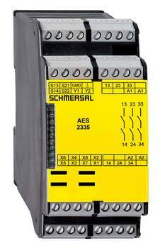
AES 2336 UE: 24...230V AC/DC
AES 2336 UE: 24...230V AC/DC-101181678
Monitoring of BNS range magnetic safety sensors3 safety contacts, STOP 02 Signalling outputs
- Monitoring of BNS range magnetic safety sensors
- 3 safety contacts, STOP 0
- 2 Signalling outputs
Ordering data
| Note (Delivery capacity) | Not available! |
| Product type description | AES 2336 UE: 24...230V AC/DC |
| Article number (order number) | 101181678 |
| EAN (European Article Number) | 4030661323091 |
| eCl@ss number, version 12.0 | 27-37-18-19 |
| eCl@ss number, version 11.0 | 27-37-18-19 |
| eCl@ss number, version 9.0 | 27-37-18-19 |
| ETIM number, version 7.0 | EC001449 |
| ETIM number, version 6.0 | EC001449 |
| Available until | 31.12.2024 |
Approvals - Standards
| cULus |
General data
| Standards | BG-GS-ET-14 BG-GS-ET-20 EN IEC 62061 EN IEC 60947-5-1 EN IEC 60947-5-3 EN IEC 60947-5-5 EN IEC 61508 EN IEC 60204-1 EN IEC 60947-1 |
| Climatic stress | EN 60068-2-3 BG-GS-ET-14 |
| Housing material | Glass-fibre, reinforced thermoplastic |
| Gross weight | 300 g |
General data - Features
| Wire breakage detection | Yes |
| Cross-circuit detection | Yes |
| Feedback circuit | Yes |
| Automatic reset function | Yes |
| Start-up test | Yes |
| Reset after disconnection of supply voltage | Yes |
| Integral system diagnostics, status | Yes |
| Number of LEDs | 1 |
| Number of normally closed (NC) | 2 |
| Number of normally open (NO) | 1 |
| Number of undelayed semi-conductor outputs with signaling function | 2 |
| Number of safety contacts | 3 |
| Number of signalling outputs | 2 |
| Safety classification |
| Standards | EN ISO 13849-1 EN IEC 61508 |
| Stop-Category | 0 |
| Safety classification - Relay outputs |
| Performance Level, up to | d |
| Category | 3 |
| PFH value | 1.00 x 10⁻⁷ /h |
| Notice | for max. 50,000 switching cycles/year and max. 80% contact load |
| Safety Integrity Level (SIL), suitable for applications in | 2 |
| Mission time | 20 Year(s) |
Mechanical data
| Mechanical life, minimum | 20,000,000 Operations |
| Mounting | Snaps onto standard DIN rail to EN 60715 |
Mechanical data - Connection technique
| Terminal designations | IEC/EN 60947-1 |
| Termination | rigid or flexible Screw terminals M20 x 1.5 |
| Cable section, minimum | 0.25 mm² |
| Cable section, maximum | 2.5 mm² |
| Tightening torque of Clips | 0.6 Nm |
Mechanical data - Dimensions
| Width | 45 mm |
| Height | 100 mm |
| Depth | 121 mm |
Ambient conditions
| Degree of protection of the enclosure | IP40 |
| Degree of protection of the mounting space | IP54 |
| Degree of protection of clips or terminals | IP20 |
| Ambient temperature | +0 ... +55 °C |
| Storage and transport temperature | -25 ... +70 °C |
| Resistance to vibrations | 10...55 Hz, Amplitude 0.35 mm, ± 15 % |
| Restistance to shock | 30 g / 11 ms |
Ambient conditions - Insulation values
| Rated impulse withstand voltage Uimp | 4 kV |
| Overvoltage category | III |
| Degree of pollution | 2 |
Electrical data
| Frequency range | 50 Hz 60 Hz |
| Type of voltage range | AC DC |
| Thermal test current | 6 A |
| Rated operating voltage | 24 ... 230 VAC |
| Rated AC voltage for controls, 50 Hz, minimum | 20.4 VAC |
| Rated control voltage at AC 50 Hz, maximum | 253 VAC |
| Rated AC voltage for controls, 60 Hz, minimum | 20.4 VAC |
| Rated control voltage at AC 60 Hz, maximum | 253 VAC |
| Rated AC voltage for controls at DC minimum | 20.4 VDC |
| Rated control voltage at DC, maximum | 253 VDC |
| Electrical power consumption | 5 W |
| Contact resistance, maximum | 0.1 Ω |
| Note (Contact resistance) | in new state |
| Drop-out delay in case of power failure, typically | 80 ms |
| Drop-out delay in case of emergency, typically | 20 ms |
| Pull-in delay at automatic start, maximum, typically | 100 ms |
| Pull-in delay at RESET, typically | 20 ms |
| Material of the contacts, electrical | Ag-Ni 10 and 0.2 µm gold-plated |
Electrical data - Safe relay outputs
| Voltage, Utilisation category AC-15 | 230 VAC |
| Current, Utilisation category AC-15 | 3 A |
| Voltage, Utilisation category DC-13 | 24 VDC |
| Current, Utilisation category DC-13 | 2 A |
| Switching capacity, minimum | 10 VDC |
| Switching capacity, minimum | 10 mA |
| Switching capacity, maximum | 250 VAC |
| Switching capacity, maximum | 8 A |
Electrical data - Digital inputs
| Input signal, HIGH Signal ″1″ | 10 … 30 VDC |
| Input signal, LOW Signal ″0″ | 0 … 2 VDC |
| Conduction resistance, maximum | 40 Ω |
Electrical data - Digital Output
| Voltage, Utilisation category DC-12 | 24 VDC |
| Current, Utilisation category DC-12 | 0.1 A |
Electrical data - Relay outputs (auxiliary contacts)
| Switching capacity, maximum | 24 VDC |
| Switching capacity, maximum | 2 A |
Electrical data - Electromagnetic compatibility (EMC)
| EMC rating | EMC-Directive |
Integral system diagnosis (ISD)
| Note (ISD -Faults) | The following faults are registered by the safety monitoring modules and indicated by ISD. |
| Faults | Failure of the safety relay to pull-in or drop-out Failure of door contacts to open or close Cross-wire or short-circuit monitoring of the switch connections Interruption of the switch connections Fault on the input circuits or the relay control circuits of the safety monitoring module Failure of or functional fault on the safety relay |
Other data
| Note (applications) | Safety sensor Guard system |
Note
| Note (General) | Inductive loads (e.g. contactors, relays, etc.) are to be suppressed by means of a suitable circuit. |
Wiring example
| Note (Wiring diagram) | The wiring diagram is shown with guard doors closed and in de-energised condition. To secure a guard door up to PL d and Category 3 The ISD tables (Intergral System Diagnostics) for analysis of the fault indications and their causes are shown in the appendix. Start push button: A start push button (NO) can optionally be connected into the feedback circuit. With the guard door closed, the enabling paths are then not closed until the start push button has been operated. Modification for 2 NC contacts: The safety monitoring module can be modified to monitor two NC contacts by bridging the terminals X3 and X4. In this configuration, the short-circuit detection becomes inoperative. Inversion of the output function: By establishing a bridge between X5 and X6, the output function of the additional outputs can be altered. This control can also be realised when e.g. a PLC is running (24 VDC at terminal X6). Expansion of the enable delay time. The enable delay time can be increased from X7 s to X8 s by mounting a jumper connection between the terminals 0,1 and 1. Monitoring a guard door using 2 position switches with safety function. The NC contact A must have positive break when the guard door is opened. Category 3 to ISO 13849-1 can also be achieved using only one safety switch with one NO and one NC contact. Exclusion of faults due to breakage or loosening of the actuating element or the actuating head as well as releasing, dismantling. The feedback circuit monitors the position of the positive-guided NC contacts of the contactors K3 and K4. If neither start button nor feedback circuit are connected, a jumper connection must be mounted between X1 and X2. |
All of our products ensure maximum reliability even in challenging working conditions and help your business operations run smoothly. The products we offer in industrial automation, energy management, cabling solutions, and many other areas adapt flexibly to the needs of different sectors.
Additionally, our products are manufactured using only high-quality materials and comply with international standards. Through the solutions we provide, we enable our customers to increase operational efficiency and optimize costs. Our company closely follows technological advancements and continuously offers innovative products to help our customers gain a competitive advantage.
On each of our product pages, you can find comprehensive information about technical details, areas of use, and product features. You can explore all the products you need to strengthen your industrial processes on our website and enjoy a seamless purchasing experience.
Similar Products


Can't find the product you're looking for?
LET US HELP YOU
Can't Find the Product You're Looking For? Let Us Know, and We'll Source It for You!
Are you searching for products not listed on our website or out of stock? Let us know your requirements, and our expert team will contact you as soon as possible to find the most suitable solution for you.