Eaton : T5-2-8211/I5
222431 T5-2-8211/I5
T5-2-8211/I5 /222431
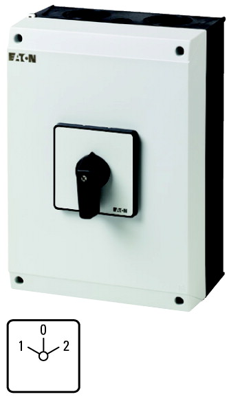
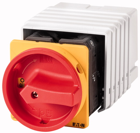
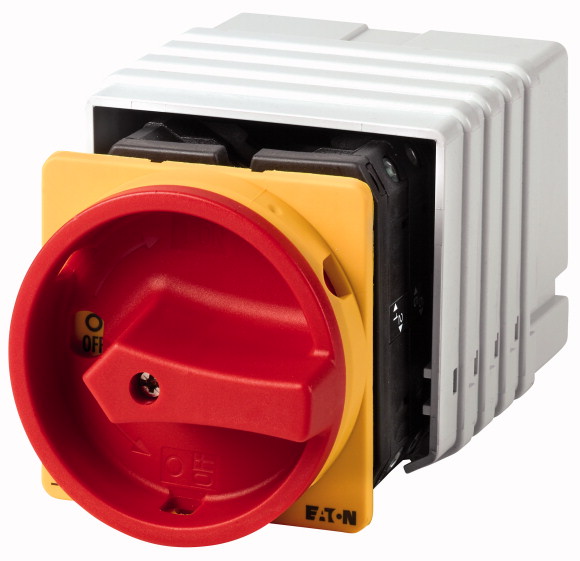
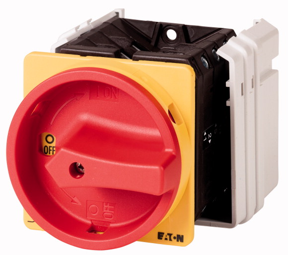
Changeoverswitches, T5, 100 A, surface mounting, 2 contact unit(s), Contacts: 4, 60 °, maintained, With 0 (Off) position, 1-0-2, Design number 8211Changeover switch, Product range: Control switches, Part group reference: T5, with black thumb grip and front plate, Contacts: 4, Degree of Protection: IP65, Design: surface mounting, Switching angle: 60 °, Switching performance: maintained, With 0 (Off) position, front plate: 1-0-2, Motor rating AC-23A, 50 - 60 Hz 400 V: P = 55 kW, Rated uninterrupted current: Iu = 100 A, 2 contact unit(s), Standards: IEC/EN 60947, VDE 0660, IEC/EN 60204, Switch-disconnector according to IEC/EN 60947-3
Changeoverswitches, T5, 100 A, surface mounting, 2 contact unit(s), Contacts: 4, 60 °, maintained, With 0 (Off) position, 1-0-2, Design number 8211
Changeover switch, Product range: Control switches, Part group reference: T5, with black thumb grip and front plate, Contacts: 4, Degree of Protection: IP65, Design: surface mounting, Switching angle: 60 °, Switching performance: maintained, With 0 (Off) position, front plate: 1-0-2, Motor rating AC-23A, 50 - 60 Hz 400 V: P = 55 kW, Rated uninterrupted current: Iu = 100 A, 2 contact unit(s), Standards: IEC/EN 60947, VDE 0660, IEC/EN 60204, Switch-disconnector according to IEC/EN 60947-3
| Product range | Control switches |
| Part group reference | T5 |
| Basic function | Changeoverswitches |
| Contacts | with black thumb grip and front plate |
| Degree of Protection | 4 |
| Design | IP65 |
| Contact sequence | |
| Switching angle | surface mounting |
| Switching performance | |
| Design number | |
| Front plate no. | 60 ° |
| front plate | maintained With 0 (Off) position |
| 400 V [P] | 8211 |
| Rated uninterrupted current [Iu] | |
| Note on rated uninterrupted current !u | 1-0-2 |
| Number of contact units | 55 kW |
| Standards | 100 A |
| Climatic proofing | Rated uninterrupted current Iu is specified for max. cross-section. |
| Ambient temperature >Enclosed |
2 contact unit(s) |
| Overvoltage category/pollution degree | IEC/EN 60947, VDE 0660, IEC/EN 60204 Switch-disconnector according to IEC/EN 60947-3 |
| Rated impulse withstand voltage [Uimp] | Damp heat, constant, to IEC 60068-2-78 Damp heat, cyclic, to IEC 60068-2-30 |
| Mechanical shock resistance | -25 - +40 °C |
| Mounting position | III/3 |
| Electrical characteristics >Rated operational voltage [Ue] |
6000 V AC |
| Electrical characteristics >Rated uninterrupted current [Iu] |
15 g |
| Electrical characteristics >Note on rated uninterrupted current !u |
As required |
| Load rating with intermittent operation, class 12 >AB 25 % DF |
690 V AC |
| Load rating with intermittent operation, class 12 >AB 40 % DF |
100 A |
| Load rating with intermittent operation, class 12 >AB 60 % DF |
Rated uninterrupted current Iu is specified for max. cross-section. |
| Short-circuit rating >Fuse |
2 x Ie |
| Rated short-time withstand current (1 s current) [Icw ] | 1.6 x Ie |
| Note on rated short-time withstand current lcw | 1.3 x Ie |
| Rated conditional short-circuit current [Iq] | 100 A gG/gL |
| cos ϕ rated making capacity as per IEC 60947-3 | 1700 Arms |
| Rated breaking capacity cos ϕ to IEC 60947-3 >230 V |
Current for a time of 1 second |
| Rated breaking capacity cos ϕ to IEC 60947-3 >400/415 V |
2 kA |
| Rated breaking capacity cos ϕ to IEC 60947-3 >500 V |
950 A |
| Rated breaking capacity cos ϕ to IEC 60947-3 >690 V |
760 A |
| Safe isolation to EN 61140 >between the contacts |
740 A |
| Safe isolation to EN 61140 >Current heat loss per contact at Ie |
590 A |
| Safe isolation to EN 61140 >Current heat loss per auxiliary circuit at Ie (AC-15/230 V) |
420 A |
| Lifespan, mechanical [Operations] | 440 V AC |
| Maximum operating frequency [Operations/h] | 7.5 W |
| AC >AC-3 >Rating, motor load switch [P] >220 V 230 V [P] |
7.5 CO |
| AC >AC-3 >Rating, motor load switch [P] >230 V Star-delta [P] |
> 0.5 x 10⁶ |
| AC >AC-3 >Rating, motor load switch [P] >400 V 415 V [P] |
1200 |
| AC >AC-3 >Rating, motor load switch [P] >400 V Star-delta [P] |
22 kW |
| AC >AC-3 >Rating, motor load switch [P] >500 V [P] |
30 kW |
| AC >AC-3 >Rating, motor load switch [P] >500 V Star-delta [P] |
30 kW |
| AC >AC-3 >Rating, motor load switch [P] >690 V [P] |
45 kW |
| AC >AC-3 >Rating, motor load switch [P] >690 V Star-delta [P] |
30 kW |
| AC >AC-3 >Rated operational current motor load switch >230 V [Ie] |
45 kW |
| AC >AC-3 >Rated operational current motor load switch >230 V star-delta [Ie] |
15 kW |
| AC >AC-3 >Rated operational current motor load switch >400V 415 V [Ie] |
22 kW |
| AC >AC-3 >Rated operational current motor load switch >400 V star-delta [Ie] |
71 A |
| AC >AC-3 >Rated operational current motor load switch >500 V [Ie ] |
100 A |
| AC >AC-3 >Rated operational current motor load switch >500 V star-delta [Ie ] |
55 A |
| AC >AC-3 >Rated operational current motor load switch >690 V [Ie] |
95.3 A |
| AC >AC-3 >Rated operational current motor load switch >690 V star-delta [Ie] |
44 A |
| AC >AC-21A >Rated operational current switch >440 V [Ie] |
76.2 A |
| AC >AC-23A >Motor rating AC-23A, 50 - 60 Hz [P] >230 V [P] |
17 A |
| AC >AC-23A >Motor rating AC-23A, 50 - 60 Hz [P] >400 V 415 V [P] |
29.4 A |
| AC >AC-23A >Motor rating AC-23A, 50 - 60 Hz [P] >500 V [P] |
100 A |
| AC >AC-23A >Motor rating AC-23A, 50 - 60 Hz [P] >690 V [P] |
30 kW |
| AC >AC-23A >Rated operational current motor load switch >230 V [Ie] |
55 kW |
| AC >AC-23A >Rated operational current motor load switch >400 V 415 V [Ie] |
37 kW |
| AC >AC-23A >Rated operational current motor load switch >500 V [Ie] |
30 kW |
| AC >AC-23A >Rated operational current motor load switch >690 V [Ie] |
100 A |
| DC >DC-1, Load-break switches L/R = 1 ms >Rated operational current [Ie] |
100 A |
| DC >DC-1, Load-break switches L/R = 1 ms >Voltage per contact pair in series |
55 A |
| Control circuit reliability at 24 V DC, 10 mA [Fault probability] | 32 A |
| Solid or stranded | 80 A |
| Flexible with ferrules to DIN 46228 | 60 V |
| Terminal screw | < 10 -5, < 1 fault in 100000 operations HF |
| Tightening torque for terminal screw | 1 x (2,5 - 35) 2 x (2,5 - 16) mm2 |
| Notes | 1 x (1 - 25) 2 x (1.5 - 10) mm2 |
| Terminal capacity >Terminal screw |
M6 |
| Rated operational current for specified heat dissipation [In] | 4 Nm |
| Heat dissipation per pole, current-dependent [Pvid] | B10d values as per EN ISO 13849-1, table C1 |
| Equipment heat dissipation, current-dependent [Pvid] | M6 |
| Static heat dissipation, non-current-dependent [Pvs] | 100 A |
| Heat dissipation capacity [Pdiss] | 7.5 W |
| Operating ambient temperature min. | 0 W |
| Operating ambient temperature max. | 0 W |
| 10.2 Strength of materials and parts >10.2.2 Corrosion resistance |
0 W |
| 10.2 Strength of materials and parts >10.2.3.1 Verification of thermal stability of enclosures |
-25 °C |
| 10.2 Strength of materials and parts >10.2.3.2 Verification of resistance of insulating materials to normal heat |
+40 °C |
| 10.2 Strength of materials and parts >10.2.3.3 Verification of resistance of insulating materials to abnormal heat and fire due to internal electric effects |
Meets the product standard´s requirements. |
| 10.2 Strength of materials and parts >10.2.4 Resistance to ultra-violet (UV) radiation |
Meets the product standard´s requirements. |
| 10.2 Strength of materials and parts >10.2.5 Lifting |
Meets the product standard´s requirements. |
| 10.2 Strength of materials and parts >10.2.6 Mechanical impact |
Meets the product standard´s requirements. |
| 10.2 Strength of materials and parts >10.2.7 Inscriptions |
UV resistance only in connection with protective shield. |
| 10.3 Degree of protection of ASSEMBLIES | Does not apply, since the entire switchgear needs to be evaluated. |
| 10.4 Clearances and creepage distances | Does not apply, since the entire switchgear needs to be evaluated. |
| 10.5 Protection against electric shock | Meets the product standard´s requirements. |
| 10.6 Incorporation of switching devices and components | Does not apply, since the entire switchgear needs to be evaluated. |
| 10.7 Internal electrical circuits and connections | Meets the product standard´s requirements. |
| 10.8 Connections for external conductors | Does not apply, since the entire switchgear needs to be evaluated. |
| 10.9 Insulation properties >10.9.2 Power-frequency electric strength |
Does not apply, since the entire switchgear needs to be evaluated. |
| 10.9 Insulation properties >10.9.3 Impulse withstand voltage |
Is the panel builder´s responsibility. |
| 10.9 Insulation properties >10.9.4 Testing of enclosures made of insulating material |
Is the panel builder´s responsibility. |
| 10.10 Temperature rise | Is the panel builder´s responsibility. |
| 10.11 Short-circuit rating | Is the panel builder´s responsibility. |
| 10.12 Electromagnetic compatibility | Is the panel builder´s responsibility. |
| 10.13 Mechanical function | The panel builder is responsible for the temperature rise calculation. Eaton will provide heat dissipation data for the devices. |
| Model | Is the panel builder´s responsibility. The specifications for the switchgear must be observed. |
| Number of poles | Is the panel builder´s responsibility. The specifications for the switchgear must be observed. |
| With 0 (off) position | The device meets the requirements, provided the information in the instruction leaflet (IL) is observed. |
| With retraction in 0-position | Reverser |
| Rated permanent current Iu | 2 |
| Rated operation current Ie at AC-3, 400 V | Yes |
| Rated operation power at AC-3, 400 V | No |
| Degree of protection (IP), front side | 100 A |
| Degree of protection (NEMA), front side | 55 A |
| Number of auxiliary contacts as normally closed contact | 30 kW |
| Number of auxiliary contacts as normally open contact | IP65 |
| Number of auxiliary contacts as change-over contact | Other |
| Suitable for ground mounting | 0 |
| Suitable for front mounting 4-hole | 0 |
| Suitable for distribution board installation | 0 |
| Suitable for intermediate mounting | Yes |
| Complete device in housing | No |
| Material housing | No |
| Type of control element | No |
| Type of electrical connection of main circuit | Yes |
All of our products ensure maximum reliability even in challenging working conditions and help your business operations run smoothly. The products we offer in industrial automation, energy management, cabling solutions, and many other areas adapt flexibly to the needs of different sectors.
Additionally, our products are manufactured using only high-quality materials and comply with international standards. Through the solutions we provide, we enable our customers to increase operational efficiency and optimize costs. Our company closely follows technological advancements and continuously offers innovative products to help our customers gain a competitive advantage.
On each of our product pages, you can find comprehensive information about technical details, areas of use, and product features. You can explore all the products you need to strengthen your industrial processes on our website and enjoy a seamless purchasing experience.
Similar Products
Can't find the product you're looking for?
LET US HELP YOU
Can't Find the Product You're Looking For? Let Us Know, and We'll Source It for You!
Are you searching for products not listed on our website or out of stock? Let us know your requirements, and our expert team will contact you as soon as possible to find the most suitable solution for you.