SKU: Eaton-EAM402H
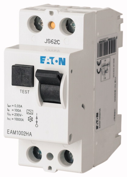
Residual current circuit-breaker; 40 A; 2-pole; 30mA; Type AC
Full range of compact residual current circuit-breaker models for a wide variety of applications, for fault and additional protection, large amount of available rated operational currents, comprehensive range of accessories, true contact position indicator, automatic reclosing possible, suitable for use outdoors (building and outdoor distribution boards) at temperatures as low as -25 °C
| Basic function | Residual current circuit-breakers |
| Number of poles | 2 pole |
| Application | Switchgear for residential and commercial applications |
| Rated current [In] | 40 A |
| Rated short-circuit strength [Icn] | 10 with back-up fuse kA |
| Rated fault current [IΔN] | 0.03 A |
| Type | Type AC |
| Tripping | non-delayed s… |
| Product range | EAM |
| Sensitivity | AC current sensitive |
| Impulse withstand current | Partly surge-proof 250 A |
| Standards | |
| Rated operational voltage [Ue] [Ue]Rated operating voltage [Ue] | IEC/EN 61008 |
| Rated frequency [f] | 230 V AC |
| Limit values of the operating voltage >Test circuit |
50 Hz |
| Sensitivity | 196 - 264 V AC |
| Rated insulation voltage [Ui ] | AC current sensitive |
| Rated impulse withstand voltage [Uimp] | 440 V |
| Rated short-circuit strength [Icn] | 4 kV |
| Rated making and breaking capacity / Rated residual making and breaking capacity [Im / IΔm] | 10 with back-up fuse kA |
| lifespan >Electrical [Operations] |
500 A |
| lifespan >Mechanical [Operations] |
≧ 4000 |
| Standard front dimension | ≧ 20000 |
| Device height | |
| Built-in width | 45 mm |
| Mounting | 80 mm |
| Degree of Protection | 35 (2TE) mm |
| Terminals top and bottom | IEC/EN 60715 top-hat rail |
| Terminal protection | IP40, IP54 (with moisture-proof enclosure) |
| Terminal cross-section >Solid |
Box clamp |
| Permissible storage and transport temperatures | DGUV VS3, EN 50274 |
| Climatic proofing | 1.5 - 35 mm2 |
| Thickness of busbar material >Material thickness |
-35 - +60 °C |
| Rated operational current for specified heat dissipation [In] | 25-55°C/90-95% relative humidity according to IEC 60068-2 |
| Heat dissipation per pole, current-dependent [Pvid] | 0.8 - 2 mm |
| Equipment heat dissipation, current-dependent [Pvid] | |
| Static heat dissipation, non-current-dependent [Pvs] | 40 A |
| Heat dissipation capacity [Pdiss] | 0 W |
| Operating ambient temperature min. | 5.8 W |
| Operating ambient temperature max. | 0 W |
| 10.2 Strength of materials and parts >10.2.2 Corrosion resistance |
0 W |
| 10.2 Strength of materials and parts >10.2.3.1 Verification of thermal stability of enclosures |
-25 °C |
| 10.2 Strength of materials and parts >10.2.3.2 Verification of resistance of insulating materials to normal heat |
+60 °C |
| 10.2 Strength of materials and parts >10.2.3.3 Verification of resistance of insulating materials to abnormal heat and fire due to internal electric effects |
Starting at 40 °C, the max. permissible continuous current decreases by 3% for every 1 °C |
| 10.2 Strength of materials and parts >10.2.4 Resistance to ultra-violet (UV) radiation |
|
| 10.2 Strength of materials and parts >10.2.5 Lifting |
Meets the product standard´s requirements. |
| 10.2 Strength of materials and parts >10.2.6 Mechanical impact |
Meets the product standard´s requirements. |
| 10.2 Strength of materials and parts >10.2.7 Inscriptions |
Meets the product standard´s requirements. |
| 10.3 Degree of protection of ASSEMBLIES | Meets the product standard´s requirements. |
| 10.4 Clearances and creepage distances | Meets the product standard´s requirements. |
| 10.5 Protection against electric shock | Does not apply, since the entire switchgear needs to be evaluated. |
| 10.6 Incorporation of switching devices and components | Does not apply, since the entire switchgear needs to be evaluated. |
| 10.7 Internal electrical circuits and connections | Meets the product standard´s requirements. |
| 10.8 Connections for external conductors | Does not apply, since the entire switchgear needs to be evaluated. |
| 10.9 Insulation properties >10.9.2 Power-frequency electric strength |
Meets the product standard´s requirements. |
| 10.9 Insulation properties >10.9.3 Impulse withstand voltage |
Does not apply, since the entire switchgear needs to be evaluated. |
| 10.9 Insulation properties >10.9.4 Testing of enclosures made of insulating material |
Does not apply, since the entire switchgear needs to be evaluated. |
| 10.10 Temperature rise | Is the panel builder´s responsibility. |
| 10.11 Short-circuit rating | Is the panel builder´s responsibility. |
| 10.12 Electromagnetic compatibility | Is the panel builder´s responsibility. |
| 10.13 Mechanical function | Is the panel builder´s responsibility. |
| Number of poles | Is the panel builder´s responsibility. |
| Rated voltage | The panel builder is responsible for the temperature rise calculation. Eaton will provide heat dissipation data for the devices. |
| Rated current | Is the panel builder´s responsibility. The specifications for the switchgear must be observed. |
| Rated fault current | Is the panel builder´s responsibility. The specifications for the switchgear must be observed. |
| Rated insulation voltage Ui | The device meets the requirements, provided the information in the instruction leaflet (IL) is observed. |
| Rated impulse withstand voltage Uimp | |
| Mounting method | |
| Leakage current type | 2 |
| Selective protection | 230 V |
| Short-time delayed tripping | 40 A |
| Short-circuit breaking capacity (Icw) | 30 mA |
| Surge current capacity | 440 V |
| Frequency | 4 kV |
| Additional equipment possible | DIN rail |
| With interlocking device | AC |
| Degree of protection (IP) | No |
| Width in number of modular spacings | No |
| Built-in depth | 10 kA |
| Ambient temperature during operating | 0.25 kA |
| Pollution degree | 50 Hz |
| Connectable conductor cross section multi-wired | Yes |
| Connectable conductor cross section solid-core | Yes |
Tüm hakları saklıdır. Mnelko Endüstriyel San. ve Tic.Ltd.Şti. 2024