SKU: Eaton-Y7-197217
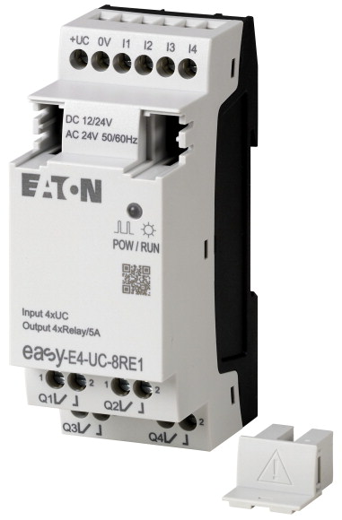
I/O expansion, For use with easyE4, 12/24 V DC, 24 V AC, Inputs expansion (number) digital: 4, screw terminal
I/O expansion, Supply voltage: 12/24 V DC, 24 V AC, Can be used via easyConnect, Mounting position: Vertical or horizontal, Protection type (IEC/EN 60529, EN50178, VBG 4): IP20, Standards: EN 61000-6-2, EN 61000-6-3, IEC 60068-2-6, IEC 60068-2-27, IEC 60068-2-30, IEC 61131-2, EN 61010, EN 50178, cULus per UL 61010, CSA C22.2 No.61010
| Product range | Control relays easyE4 |
| Subrange | easyE4 digital input/output enhancements |
| Basic function | easyE4 extensions |
| Description | Input/output extension for easyE4 control relay Expandable with the easyE4 series of digital input/output expansions with easy-E4-CONNECT1 connector (Item Y7-197225) Rated operating voltage 12V DC, 24V DC or 24V AC Digital inputs: 4 Digital outputs: 4 relays Screw terminals |
| Inputs expansion (number) | |
| Display | digital: 4 |
| Software | |
| Supply voltage | with diagnostic LED |
| For use with | EASYSOFT-SWLIC/easySoft 7 |
| Standards | 12/24 V DC 24 V AC |
| Approvals >Approvals |
easyE4 |
| Approvals >certificate |
|
| Approvals >shipping classification |
EN 61000-6-2 EN 61000-6-3 IEC 60068-2-6 IEC 60068-2-27 IEC 60068-2-30 IEC 61131-2 EN 61010 EN 50178 |
| Approvals | cULus |
| Dimensions (W x H x D) | CE |
| Weight | DNV GL |
| Mounting | |
| Connection type | 35.5 x 90 x 58 mm |
| Screw terminals >Solid |
0.125 kg |
| Screw terminals >flexible |
Top-hat rail IEC/EN 60715, 35 mm or screw fixing using fixing brackets ZB4-101-GF1 (accessories) |
| Screw terminals >Solid or flexible conductor, with ferrule |
Push-in terminals |
| Screw terminals >Solid or stranded |
|
| Screw terminals >Standard screwdriver |
0.2 - 4 mm2 |
| Screw terminals >Tightening torque |
0.2 - 2.5 mm2 |
| Screw terminals >Stripping length |
0,2 - 2,5 mm2 |
| Operating ambient temperature | 22 - 12 AWG |
| Condensation | 0.8 x 3.5 mm |
| Storage [ϑ] | 0.5 - 0.7 Nm |
| relative humidity | 6.5 mm |
| Air pressure (operation) | |
| Protection type (IEC/EN 60529, EN50178, VBG 4) | -25 to 55, cold as per IEC 60068-2-1, heat as per IEC 60068-2-2 °C |
| Vibrations | Take appropriate measures to prevent condensation |
| Mechanical shock resistance (IEC/EN 60068-2-27) semi-sinusoidal 15 g/11 ms | -40 - +70 °C |
| Drop to IEC/EN 60068-2-31 [Drop height] | in accordance with IEC 60068-2-30, IEC 60068-2-78 5 - 95 % |
| Free fall, packaged (IEC/EN 60068-2-32) | 795 - 1080 hPa |
| Mounting position | |
| Overvoltage category/pollution degree | IP20 |
| Electrostatic discharge (ESD) >applied standard |
In accordance with IEC 60068-2-6 constant amplitude 0.15 mm: 10 - 57 constant acceleration 2 g: 57 - 150 Hz |
| Electrostatic discharge (ESD) >Air discharge |
18 Impacts |
| Electrostatic discharge (ESD) >Contact discharge |
50 mm |
| Electromagnetic fields (RFI) to IEC EN 61000-4-3 | 0.3 m |
| Radio interference suppression | Vertical or horizontal |
| Burst | |
| power pulses (Surge) | III/2 |
| Immunity to line-conducted interference to (IEC/EN 61000-4-6) | according to IEC EN 61000-4-2 |
| Clearance in air and creepage distances | 8 kV |
| Insulation resistance | 6 kV |
| Rated operational voltage [Ue] | 0.8 - 1.0 GHz: 10 1.4 - 2 GHz: 3 2.0 - 2.7 GHz: 1 V/m |
| Permissible range [Ue] | EN 61000-6-3 Class B |
| Residual ripple | according to IEC/EN 61000-4-4 Supply cables: 2 Signal cables: 2 kV |
| Protection against polarity reversal | according to IEC/EN 61000-4-5 1 kV (supply cables, symmetrical) 2 kV (supply cables, asymmetrical) |
| Frequency | 10 V |
| Input current | |
| Voltage dips | nach EN 50178, EN 61010-2-201, UL61010-2-201, CSA-C22.2 NO. 61010-2-201 |
| Fuse | in accordance with EN 50178, EN 61010-2-201, UL61010-2-201, CSA-C22.2 NO. 61010-2-201 |
| Power loss [P] | |
| Heat dissipation at 24 V DC | 12/24 DC (-15/+20%) 24 AC (-15/+10%) V |
| Number | 10.2 - 28.8 V DC 20.4 - 26.4 V AC |
| Potential isolation | ≦ 5 % |
| Rated operational voltage [Ue] | yes |
| Input voltage | 50/60 (± 5%) Hz |
| Input current at signal 1 | max. 150 mA at 12 V DC max. 80 mA at 24 V DC |
| Deceleration time | ≤ 20 ms at 24 V AC 10 ms at 24 V DC 1 ms at 12 V DC ms |
| Cable length | ≧ 1A (T) A |
| Number | Normally 2 W |
| Potential isolation | 2 W |
| Rated operational voltage [Ue] | |
| Input voltage | 4 |
| Input current at signal 1 | from power supply: no between inputs: no from the outputs: yes to base unit: yes to expansion devices: yes |
| Deceleration time | 12 V DC |
| Cable length | Status 0: ≦ 5 (I1 - I4) Condition 1: ≧ 8 (I1 - I4) V DC |
| Number | 1.75 mA (I1 - I4) mA |
| Potential isolation | type 0.2 (0 -> 1) type 0.15 (1 -> 0) ms |
| Rated operational voltage [Ue] | 100 (unshielded) m |
| Input voltage (AC = sinusoidal) [Ue] | |
| Rated frequency | 4 |
| Input current at signal 1 | from power supply: no between inputs: no from the outputs: yes to base unit: yes to expansion devices: yes |
| Deceleration time | 24 V DC |
| Cable length | Signal 0: ≦ 5 (I1 - I4) Signal 1: ≧ 15 (I1 - I4) V DC |
| Number | 3.3 (I1 – I4) mA |
| Outputs in groups of | type 0.1 (0 -> 1) type 0.2 (1 -> 0) ms |
| Parallel switching of outputs for increased output | 100 (unshielded) m |
| Protection of an output relay | |
| Potential isolation | 4 |
| Contacts >Conventional thermal current (10 A UL) |
from power supply: no between inputs: no from the outputs: yes to base unit: yes to expansion devices: yes |
| Contacts >Recommended for load: 12 V AC/DC |
24 V AC |
| Contacts >Rated impulse withstand voltage Uimp of contact coil |
Status 0: ≦ 5 (I1 - I8) Condition 1: ≧ 14 (I1 - I4) V |
| Contacts >Rated operational voltage [Ue] |
50/60 Hz |
| Rated insulation voltage [Ui] | I1 - I4: 3.5 (at 24 VAC/DC) mA |
| Safe isolation according to EN 50178 | type 25⁄21 (0 - > 1/1 -> 0, 50/60Hz) ms |
| Making capacity >AC–-15, 250 V AC, 3 A (600 ops./h) [Operations] |
40 (unshielded) m |
| Making capacity >DC-13, L/R ≦ 150 ms, 24 V DC, 1 A (500 S/h) [Operations] |
|
| Breaking capacity >AC-15, 250 V AC, 3 A (600 Ops./h) [Operations] |
4 |
| Breaking capacity >DC-13, L/R ≦ 150 ms, 24 V DC, 1 A (500 S/h) [Operations] |
1 |
| Filament bulb load >1000 W at 230/240 V AC [Operations] |
Not permitted |
| Filament bulb load >500 W at 115/120 V AC [Operations] |
B16 circuit breaker or 8 A (T) fuse |
| Fluorescent lamp load >Fluorescent lamp load 10 x 58 W at 230/240 V AC >With upstream electrical device [Operations] |
Safe isolation according to EN 50178: 300 V AC Basic isolation: 600 V AC from power supply: yes From the inputs: yes between outputs: yes to expansion devices: yes |
| Fluorescent lamp load >Fluorescent lamp load 10 x 58 W at 230/240 V AC >Uncompensated [Operations] |
5 A |
| Fluorescent lamp load >Fluorescent lamp load 1 x 58 W at 230/240 V AC, conventional, compensated [Operations] |
> 500 mA |
| Switching frequency >Mechanical operations |
6 kV |
| Switching frequency >Switching frequency |
240 V AC |
| Switching frequency >Resistive load/lamp load |
240 V AC |
| Switching frequency >Inductive load |
300 between coil and contact 300 between two contacts V AC |
| UL/CSA >Uninterrupted current at 240 V AC |
300000 |
| UL/CSA >Uninterrupted current at 24 V DC |
200000 |
| UL/CSA >AC >Control Circuit Rating Codes (utilization category) |
300000 |
| UL/CSA >AC >Max. rated operational voltage |
200000 |
| UL/CSA >AC >max. thermal continuous current cos ϕ = 1 at B 300 |
25000 |
| UL/CSA >AC >max. make/break cos ϕ ≠ capacity 1 at B 300 |
25000 |
| UL/CSA >DC >Control Circuit Rating Codes (utilization category) |
25000 |
| UL/CSA >DC >Max. rated operational voltage |
25000 |
| UL/CSA >DC >Max. thermal uninterrupted current at R 300 |
25000 |
| UL/CSA >DC >Max. make/break capacity at R 300 |
10 x 106 |
| Power loss [P] | 10 Hz |
| Static heat dissipation, non-current-dependent [Pvs] | 2 Hz |
| Operating ambient temperature min. | 0.5 Hz |
| Operating ambient temperature max. | 5 A |
| 10.2 Strength of materials and parts >10.2.2 Corrosion resistance |
5 A |
| 10.2 Strength of materials and parts >10.2.3.1 Verification of thermal stability of enclosures |
B 300 Light Pilot Duty |
| 10.2 Strength of materials and parts >10.2.3.2 Verification of resistance of insulating materials to normal heat |
300 V AC |
| 10.2 Strength of materials and parts >10.2.3.3 Verification of resistance of insulating materials to abnormal heat and fire due to internal electric effects |
5 A |
| 10.2 Strength of materials and parts >10.2.4 Resistance to ultra-violet (UV) radiation |
3600/360 VA |
| 10.2 Strength of materials and parts >10.2.5 Lifting |
R 300 Light Pilot Duty |
| 10.2 Strength of materials and parts >10.2.6 Mechanical impact |
300 V DC |
| 10.2 Strength of materials and parts >10.2.7 Inscriptions |
1 A |
| 10.3 Degree of protection of ASSEMBLIES | 28/28 VA |
| 10.4 Clearances and creepage distances | |
| 10.5 Protection against electric shock | 2 W |
| 10.6 Incorporation of switching devices and components | |
| 10.7 Internal electrical circuits and connections | 2 W |
| 10.8 Connections for external conductors | -25 °C |
| 10.9 Insulation properties >10.9.2 Power-frequency electric strength |
+55 °C |
| 10.9 Insulation properties >10.9.3 Impulse withstand voltage |
|
| 10.9 Insulation properties >10.9.4 Testing of enclosures made of insulating material |
Meets the product standard´s requirements. |
| 10.10 Temperature rise | Meets the product standard´s requirements. |
| 10.11 Short-circuit rating | Meets the product standard´s requirements. |
| 10.12 Electromagnetic compatibility | Meets the product standard´s requirements. |
| 10.13 Mechanical function | Meets the product standard´s requirements. |
| Supply voltage AC 50 Hz | Does not apply, since the entire switchgear needs to be evaluated. |
| Supply voltage AC 60 Hz | Does not apply, since the entire switchgear needs to be evaluated. |
| Supply voltage DC | Meets the product standard´s requirements. |
| Voltage type of supply voltage | Meets the product standard´s requirements. |
| Switching current | Meets the product standard´s requirements. |
| Number of analogue inputs | Does not apply, since the entire switchgear needs to be evaluated. |
| Number of analogue outputs | Does not apply, since the entire switchgear needs to be evaluated. |
| Number of digital inputs | Is the panel builder´s responsibility. |
| Number of digital outputs | Is the panel builder´s responsibility. |
| With relay output | Is the panel builder´s responsibility. |
| Number of HW-interfaces industrial Ethernet | Is the panel builder´s responsibility. |
| Number of interfaces PROFINET | Is the panel builder´s responsibility. |
| Number of HW-interfaces RS-232 | The panel builder is responsible for the temperature rise calculation. Eaton will provide heat dissipation data for the devices. |
| Number of HW-interfaces RS-422 | Is the panel builder´s responsibility. |
| Number of HW-interfaces RS-485 | Is the panel builder´s responsibility. |
| Number of HW-interfaces serial TTY | The device meets the requirements, provided the information in the instruction leaflet (IL) is observed. |
| Number of HW-interfaces USB | |
| Number of HW-interfaces parallel | |
| Number of HW-interfaces Wireless | 20.4 - 28.8 V |
| Number of HW-interfaces other | 20.4 - 28.8 V |
| With optical interface | 10.2 - 28.8 V |
| Supporting protocol for TCP/IP | AC/DC |
| Supporting protocol for PROFIBUS | 5 A |
| Supporting protocol for CAN | 0 |
| Supporting protocol for INTERBUS | 0 |
| Supporting protocol for ASI | 4 |
| Supporting protocol for KNX | 4 |
| Supporting protocol for MODBUS | Yes |
| Supporting protocol for Data-Highway | 0 |
| Supporting protocol for DeviceNet | 0 |
| Supporting protocol for SUCONET | 0 |
| Supporting protocol for LON | 0 |
| Supporting protocol for PROFINET IO | 0 |
| Supporting protocol for PROFINET CBA | 0 |
| Supporting protocol for SERCOS | 0 |
| Supporting protocol for Foundation Fieldbus | 0 |
| Supporting protocol for EtherNet/IP | 0 |
| Supporting protocol for AS-Interface Safety at Work | 2 |
| Supporting protocol for DeviceNet Safety | No |
| Supporting protocol for INTERBUS-Safety | No |
| Supporting protocol for PROFIsafe | No |
| Supporting protocol for SafetyBUS p | No |
| Supporting protocol for other bus systems | No |
| Radio standard Bluetooth | No |
| Radio standard WLAN 802.11 | No |
| Radio standard GPRS | No |
| Radio standard GSM | No |
| Radio standard UMTS | No |
| IO link master | No |
| Redundancy | No |
| With display | No |
| Degree of protection (IP) | No |
| Basic device | No |
| Expandable | No |
| Expansion device | No |
| With timer | No |
| Rail mounting possible | No |
| Wall mounting/direct mounting | No |
| Front build in possible | No |
| Rack-assembly possible | No |
| Suitable for safety functions | No |
| Category according to EN 954-1 | No |
| SIL according to IEC 61508 | No |
| Performance level acc. EN ISO 13849-1 | No |
| Appendant operation agent (Ex ia) | No |
| Appendant operation agent (Ex ib) | No |
| Explosion safety category for gas | No |
| Explosion safety category for dust | No |
| Width | No |
| Height | IP20 |
| Depth | No |
| UL File No. | Yes |
| UL Category Control No. | Yes |
| North America Certification | No |
| Degree of Protection | Yes |
Tüm hakları saklıdır. Mnelko Endüstriyel San. ve Tic.Ltd.Şti. 2024