SKU: Eaton-Y7-197213
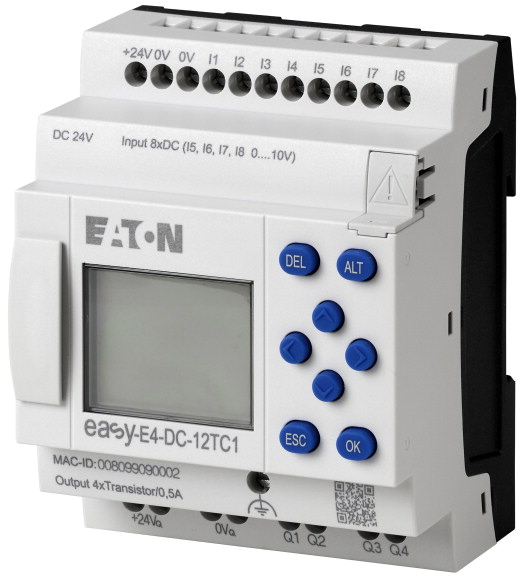
Control relays easyE4 with display (expandable, Ethernet), 24 V DC, Inputs Digital: 8, of which can be used as analog: 4, screw terminal
Electronic control relay easy-E4 with supply voltage 24 VDC. 8 digital inputs with 24VDC are available, of which 4 inputs can also be used as analog inputs and 4 inputs as fast counter. The control relay easy-E4 has 4 transitor outputs for 24 VDC. The control relay is equipped with a display, a clock, an integrated Ethernet interface and screw terminals. This control relay easy-E4 can be extended with the digital input/output extensions of the easyE4 series. A delivery with its own user program is possible via article (Y7) -2010781 EASY-COMBINATION.
| Basic function | easyE4 base device |
| Description | Electronic control relay with display with Ethernet interface Expandable with the easyE4 series of digital input/output expansions with easy-E4-CONNECT1 connector (Item Y7-197225) Rated operating voltage 24V DC 8 digital inputs, No. of these can be used as analog inputs - 4 Digital outputs: 4 transistor Screw terminals Delivery with customized user program is possible via Item (Y7) -2010781 EASY-COMBINATION |
| Digital | |
| of which can be used as analog | 8 |
| Quantity of outputs | 4 |
| Real time clock | |
| Display & keypad | Transistor: 4 |
| Expansions | |
| Supply voltage | ✔ |
| Software | ✔ |
| Connection type | Expandable networkable (Ethernet) |
| Standards | 24 V DC |
| Approvals >Approvals |
EASYSOFT-SWLIC/easySoft 7 |
| Approvals >certificate |
screw terminal |
| Approvals >shipping classification |
|
| Approvals | EN 61000-6-2 EN 61000-6-3 IEC 60068-2-6 IEC 60068-2-27 IEC 60068-2-30 IEC 61131-2 EN 61010 EN 50178 |
| Dimensions (W x H x D) | cULus |
| Weight | CE |
| Mounting | DNV GL |
| Connection type | |
| Ethernet >Connections |
71.5 x 90 x 58 mm |
| Ethernet >Cable |
0.178 kg |
| Screw terminals >Solid |
Top-hat rail IEC/EN 60715, 35 mm or screw fixing using fixing brackets ZB4-101-GF1 (accessories) |
| Screw terminals >flexible |
screw terminal |
| Screw terminals >Solid or flexible conductor, with ferrule |
RJ45 plug, 8-pin |
| Screw terminals >Solid or stranded |
CAT5 |
| Screw terminals >Standard screwdriver |
|
| Screw terminals >Tightening torque |
0.2 - 4 mm2 |
| Screw terminals >Stripping length |
0.2 - 2.5 mm2 |
| Display - Type | 0,2 - 2,5 mm2 |
| Lines x characters | 22 - 12 AWG |
| Operating ambient temperature | 0.8 x 3.5 mm |
| Condensation | 0.5 - 0.7 Nm |
| LCD display (clearly legible) | 6.5 mm |
| Storage [ϑ] | |
| relative humidity | Monochrome |
| Air pressure (operation) | 6 x 16 |
| Protection type (IEC/EN 60529, EN50178, VBG 4) | |
| Vibrations | -25 to 55, cold as per IEC 60068-2-1, heat as per IEC 60068-2-2 °C |
| Mechanical shock resistance (IEC/EN 60068-2-27) semi-sinusoidal 15 g/11 ms | Take appropriate measures to prevent condensation |
| Drop to IEC/EN 60068-2-31 [Drop height] | 0 - 55 °C |
| Free fall, packaged (IEC/EN 60068-2-32) | -40 - +70 °C |
| Mounting position | in accordance with IEC 60068-2-30, IEC 60068-2-78 5 - 95 % |
| Overvoltage category/pollution degree | 795 - 1080 hPa |
| Electrostatic discharge (ESD) >applied standard |
|
| Electrostatic discharge (ESD) >Air discharge |
IP20 |
| Electrostatic discharge (ESD) >Contact discharge |
In accordance with IEC 60068-2-6 constant amplitude 0.15 mm: 10 - 57 constant acceleration 2 g: 57 - 150 Hz |
| Electromagnetic fields (RFI) to IEC EN 61000-4-3 | 18 Impacts |
| Radio interference suppression | 50 mm |
| Burst | 0.3 m |
| power pulses (Surge) | Vertical or horizontal |
| Immunity to line-conducted interference to (IEC/EN 61000-4-6) | |
| Clearance in air and creepage distances | III/2 |
| Insulation resistance | according to IEC EN 61000-4-2 |
| Back-up of real-time clock | 8 kV |
| Accuracy of real-time clock to inputs | 6 kV |
| Accuracy of timing relays (of values) | 0.8 - 1.0 GHz: 10 1.4 - 2 GHz: 3 2.0 - 2.7 GHz: 1 V/m |
| Resolution >Range “S” |
EN 61000-6-3 Class B |
| Resolution >Range “M:S” |
according to IEC/EN 61000-4-4 Supply cables: 2 Signal cables: 2 kV |
| Resolution >Range “H:M” |
according to IEC/EN 61000-4-5 0.5 kV (supply cables, symmetrical) 1 kV (supply cables, asymmetrical) |
| Rated operational voltage [Ue] | 10 V |
| Permissible range [Ue] | |
| Residual ripple | nach EN 50178, EN 61010-2-201, UL61010-2-201, CSA-C22.2 NO. 61010-2-201 |
| Protection against polarity reversal | per EN 50178, EN 61010-2-201, UL61010-2-201, CSA-C22.2 NO. 61010-2-201 |
| Input current | |
| Voltage dips | |
| Fuse | ① Backup time (hours) with fully charged double layer capacitor ② Service life (years) |
| Power loss [P] | typ. ± 2 (± 0.2 h⁄Year) s/day |
| Heat dissipation at 24 V DC | depending on ambient air temperature fluctuations of up to ± 5 s/day (± 0.5 h⁄year) are possible |
| Number | |
| Inputs can be used as analog inputs | ± 0.02 % |
| Status Display | 5 ms |
| Potential isolation | 1 s |
| Rated operational voltage [Ue] | 1 min |
| Input voltage | |
| Input current at signal 1 | 24 DC (-15/+20%) V |
| Deceleration time | 20.4 - 28.8 V DC |
| Cable length | ≦ 5 % |
| Frequency counter >Number |
yes |
| Frequency counter >Counter frequency |
max. 80 mA at Ue |
| Frequency counter >Pulse shape |
≤ 10 ms |
| Frequency counter >Pulse pause ratio |
≧ 1A (T) A |
| Frequency counter >Cable length |
Normally 2 W |
| Incremental counter >Number of counter inputs |
2 W |
| Incremental counter >Value range |
|
| Incremental counter >Counter frequency |
8 |
| Incremental counter >Pulse shape |
4 (I5, I6, I7, I8) |
| Incremental counter >Signal offset |
LCD-Display |
| Incremental counter >Pulse pause ratio |
from power supply: no to the memory card: no to Ethernet: yes between inputs: no from the outputs: yes to expansion devices: yes |
| Incremental counter >Cable length |
24 V DC |
| Rapid counter inputs >Number |
Signal 0: ≦ 5 (I1 - I8) Condition 1: ≧ 15 (I1 - I8) V DC |
| Rapid counter inputs >Value range |
3.3 (I1 – I4) 1.8 (I5 – I8) mA |
| Rapid counter inputs >Counter frequency |
20 (0 -> 1/1 -> 0, Debounce ON) type 0.015 (0 -> 1/1 -> 0, Debounce OFF) ms |
| Rapid counter inputs >Pulse shape |
100 (unshielded) m |
| Rapid counter inputs >Pulse pause ratio |
4 (I1, I2, I3, I4) |
| Rapid counter inputs >Cable length |
≦ 5 kHz |
| Number | Square |
| Potential isolation | 1:1 |
| Input type | ≦ 20 (screened) m |
| Signal range | 2 (I1 + I2, I3 + I4) |
| Resolution | -2147483648 to +2147483647 |
| Input impedance | ≦ 5 kHz |
| Accuracy of actual value >two devices from series |
Square |
| Accuracy of actual value >Within a single device |
90° |
| Conversion time, analog/digital | 1:1 |
| Input current | ≦ 20 (screened) m |
| Cable length | 4 (I1, I2, I3, I4) |
| Number | -2147483648 to +2147483647 |
| Rated operational voltage [Ue] | ≦ 10 kHz |
| Permissible range [Ue] | Square |
| Residual ripple | 1:1 |
| Supply current | ≦ 20 (screened) m |
| Protection against polarity reversal | |
| Potential isolation | 4 (I5, I6, I7, I8) |
| Rated operational current at signal „1” DC per channel [Ie] | from power supply: no to the memory card: no to Ethernet: yes between inputs: no from the outputs: yes to expansion devices: yes |
| Residual current on 0 signal per channel | DC voltage |
| Max. output voltage | 0-10 V DC |
| Short-circuit protection | 12 Bit (value 0 - 4095) |
| Short-circuit tripping current for Ra ≦ 10 mΩ | 13.3 kΩ |
| Total short-circuit current | ± 3 , ± 0.12 V % |
| Thermal cutout | ± 2, ± 0.12 V % |
| Max. operating frequency with constant resistive load | each CPU cycle ms |
| Parallel connection of outputs >With resistive load, inductive load with external suppressor circuit, combination within a group |
< 1 mA |
| Parallel connection of outputs >Number of outputs [max.] |
≦ 30, screened m |
| Parallel connection of outputs >Max. total current |
|
| Output status indication | 4 |
| Inductive load to EN 60947-5-1 >Without external suppressor circuit >DC-13, T0.95 = 72 ms, R = 48 Ω, L = 1.15 H >Utilization factor |
24 V DC |
| Inductive load to EN 60947-5-1 >Without external suppressor circuit >DC-13, T0.95 = 72 ms, R = 48 Ω, L = 1.15 H >Duty factor |
20.4 - 28.8 V DC |
| Inductive load to EN 60947-5-1 >Without external suppressor circuit >T0.95 = 15 ms, R = 48 Ω, L = 0.24 H >Utilization factor |
5 % |
| Inductive load to EN 60947-5-1 >Without external suppressor circuit >T0.95 = 15 ms, R = 48 Ω, L = 0.24 H >Duty factor |
Norm./max. 15 mA |
| Inductive load to EN 60947-5-1 >With external suppressor circuit >Utilization factor |
Yes (Caution: A short circuit will occur if a supply voltage of the wrong polarity is applied to the outputs.) |
| Inductive load to EN 60947-5-1 >With external suppressor circuit >Duty factor |
from power supply: yes to the memory card: yes to Ethernet: yes From the inputs: yes to control buttons: yes between the outputs: no to expansion devices: yes |
| Inductive load to EN 60947-5-1 >With external suppressor circuit >Max. switching frequency, max. duty factor |
Max. 0.5 A |
| Power loss [P] | < 0.005 mA |
| Data transfer rate | 1 (at status 0 per channel) U = Ue - 1 V (signal 1 at Ie = 0.5 A) V |
| Connections | yes, electronic (Q1 - Q4) |
| Cable | 0.7 ≦ Ie ≦ 1.7 per output depending on number of active channels and their load A |
| Static heat dissipation, non-current-dependent [Pvs] | 6.8 A |
| Operating ambient temperature min. | Yes |
| Operating ambient temperature max. | abhängig von der Zykluszeit des Basisgeräts und bei Erweiterungsgeräten auch von deren Übertragungszeit Operations/h |
| 10.2 Strength of materials and parts >10.2.2 Corrosion resistance |
Group 1: Q1 to Q4 |
| 10.2 Strength of materials and parts >10.2.3.1 Verification of thermal stability of enclosures |
4 |
| 10.2 Strength of materials and parts >10.2.3.2 Verification of resistance of insulating materials to normal heat |
2 A |
| 10.2 Strength of materials and parts >10.2.3.3 Verification of resistance of insulating materials to abnormal heat and fire due to internal electric effects |
LCD-display |
| 10.2 Strength of materials and parts >10.2.4 Resistance to ultra-violet (UV) radiation |
0.25 g |
| 10.2 Strength of materials and parts >10.2.5 Lifting |
100 % DF |
| 10.2 Strength of materials and parts >10.2.6 Mechanical impact |
0.25 g |
| 10.2 Strength of materials and parts >10.2.7 Inscriptions |
100 % DF |
| 10.3 Degree of protection of ASSEMBLIES | 1 g |
| 10.4 Clearances and creepage distances | 100 % DF |
| 10.5 Protection against electric shock | Depending on the suppressor circuit Operations |
| 10.6 Incorporation of switching devices and components | |
| 10.7 Internal electrical circuits and connections | 2 W |
| 10.8 Connections for external conductors | |
| 10.9 Insulation properties >10.9.2 Power-frequency electric strength |
10/100 Mbit/s |
| 10.9 Insulation properties >10.9.3 Impulse withstand voltage |
RJ45 plug, 8-pin |
| 10.9 Insulation properties >10.9.4 Testing of enclosures made of insulating material |
CAT5 |
| 10.10 Temperature rise | |
| 10.11 Short-circuit rating | 2 W |
| 10.12 Electromagnetic compatibility | -25 °C |
| 10.13 Mechanical function | +55 °C |
| Supply voltage AC 50 Hz | |
| Supply voltage AC 60 Hz | Meets the product standard´s requirements. |
| Supply voltage DC | Meets the product standard´s requirements. |
| Voltage type of supply voltage | Meets the product standard´s requirements. |
| Switching current | Meets the product standard´s requirements. |
| Number of analogue inputs | Meets the product standard´s requirements. |
| Number of analogue outputs | Does not apply, since the entire switchgear needs to be evaluated. |
| Number of digital inputs | Does not apply, since the entire switchgear needs to be evaluated. |
| Number of digital outputs | Meets the product standard´s requirements. |
| With relay output | Meets the product standard´s requirements. |
| Number of HW-interfaces industrial Ethernet | Meets the product standard´s requirements. |
| Number of interfaces PROFINET | Does not apply, since the entire switchgear needs to be evaluated. |
| Number of HW-interfaces RS-232 | Does not apply, since the entire switchgear needs to be evaluated. |
| Number of HW-interfaces RS-422 | Is the panel builder´s responsibility. |
| Number of HW-interfaces RS-485 | Is the panel builder´s responsibility. |
| Number of HW-interfaces serial TTY | Is the panel builder´s responsibility. |
| Number of HW-interfaces USB | Is the panel builder´s responsibility. |
| Number of HW-interfaces parallel | Is the panel builder´s responsibility. |
| Number of HW-interfaces Wireless | The panel builder is responsible for the temperature rise calculation. Eaton will provide heat dissipation data for the devices. |
| Number of HW-interfaces other | Is the panel builder´s responsibility. |
| With optical interface | Is the panel builder´s responsibility. |
| Supporting protocol for TCP/IP | The device meets the requirements, provided the information in the instruction leaflet (IL) is observed. |
| Supporting protocol for PROFIBUS | |
| Supporting protocol for CAN | |
| Supporting protocol for INTERBUS | 0 - 0 V |
| Supporting protocol for ASI | 0 - 0 V |
| Supporting protocol for KNX | 20.4 - 28.8 V |
| Supporting protocol for MODBUS | DC |
| Supporting protocol for Data-Highway | 0.5 A |
| Supporting protocol for DeviceNet | 4 |
| Supporting protocol for SUCONET | 0 |
| Supporting protocol for LON | 8 |
| Supporting protocol for PROFINET IO | 4 |
| Supporting protocol for PROFINET CBA | No |
| Supporting protocol for SERCOS | 1 |
| Supporting protocol for Foundation Fieldbus | 0 |
| Supporting protocol for EtherNet/IP | 0 |
| Supporting protocol for AS-Interface Safety at Work | 0 |
| Supporting protocol for DeviceNet Safety | 0 |
| Supporting protocol for INTERBUS-Safety | 0 |
| Supporting protocol for PROFIsafe | 0 |
| Supporting protocol for SafetyBUS p | 0 |
| Supporting protocol for other bus systems | 0 |
| Radio standard Bluetooth | 1 |
| Radio standard WLAN 802.11 | No |
| Radio standard GPRS | Yes |
| Radio standard GSM | No |
| Radio standard UMTS | No |
| IO link master | No |
| Redundancy | No |
| With display | No |
| Degree of protection (IP) | Yes |
| Basic device | No |
| Expandable | No |
| Expansion device | No |
| With timer | No |
| Rail mounting possible | No |
| Wall mounting/direct mounting | No |
| Front build in possible | No |
| Rack-assembly possible | No |
| Suitable for safety functions | No |
| Category according to EN 954-1 | No |
| SIL according to IEC 61508 | No |
| Performance level acc. EN ISO 13849-1 | No |
| Appendant operation agent (Ex ia) | No |
| Appendant operation agent (Ex ib) | No |
| Explosion safety category for gas | No |
| Explosion safety category for dust | No |
| Width | No |
| Height | No |
| Depth | No |
| UL File No. | No |
| UL Category Control No. | No |
| North America Certification | No |
| Degree of Protection | Yes |
Tüm hakları saklıdır. Mnelko Endüstriyel San. ve Tic.Ltd.Şti. 2024