SKU: Eaton-192383
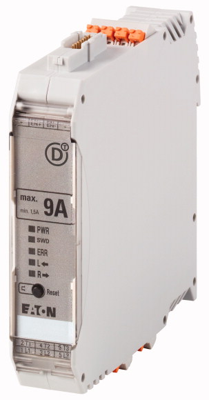
DOL starter, 24 V DC, 0,18 - 3 A, Push in terminals, SmartWire-DT slave
DOL starter, Product range: Electronic motor starter, SmartWire-DT slave, Function: For connecting to SmartWire-DT for expanded diagnostics, Description: DOL starting, Motor protection, Circuit design: safety output stage with bypass, three-phase disconnect., Motor current additionally adjustable via SmartWire-DT., Motor ratings Max. rating for three-phase motors, 50 - 60 Hz AC-53a 380 V 400 V 415 V: P= 0.06 - 0.75 kW, Setting range of overload releases: Ir= 0,18 - 3 A_x, Actuating voltage: 24 V DC, Connection technique: Push in terminals, Connection to SmartWire-DT: yes, Mounting position: Vertical, Motor feeder at bottom, Standards: IEC/EN 60947-4-2, UL508
| Product range | Electronic motor starter |
| Product range | SmartWire-DT slave |
| Subrange | SmartWire-DT electronic motor starters |
| Basic function | DOL starters (complete devices) |
| Function | For connecting to SmartWire-DT for expanded diagnostics |
| Description | DOL starting Motor protection Circuit design: safety output stage with bypass, three-phase disconnect. Motor current additionally adjustable via SmartWire-DT. |
| Messages | Operational readiness Operating direction feedback Motor current in % Motor current in A Thermal motor image in % Overload prewarning Trip indications (overload, phase failure, etc.) Set short-circuit release value Device Type |
| Commands | Operating the motor starter Manual reset Automatic reset |
| Max. rating for three-phase motors, 50 - 60 Hz >AC-53a >380 V 400 V 415 V [P] |
|
| Setting range of overload releases |
0.06 - 1.1 kW |
| Actuating voltage | 0,18 - 3 A_x |
| Connection technique | 24 V DC |
| Connection to SmartWire-DT | Push in terminals |
| Standards | yes |
| Ambient temperature >Storage >Min. ambient temperature, storage |
|
| Ambient temperature >Storage >Ambient temperature, storage max. |
IEC/EN 60947-4-2 UL508 |
| Ambient temperature >Open >Operating ambient temperature min. |
- 40 °C |
| Ambient temperature >Open >Operating ambient temperature max. |
+ 80 °C |
| Weight | -5 °C |
| Mounting | +55 °C |
| Protection type (IEC/EN 60529, EN50178, VBG 4) | 0.22 kg |
| Mounting position | Top-hat rail IEC/EN 60715, 35 mm |
| Terminal capacity >Push-in terminals |
IP20 |
| Terminal capacity >Push-in terminals |
Vertical Motor feeder at bottom |
| Rated operational voltage [Ue] | 0.2 - 2.5 mm2 |
| Operational voltage range >Operating voltage range min. |
24 - 14 AWG |
| Operational voltage range >Operating voltage range max. |
|
| Rated operational current >AC-51 [Ie] |
500 V AC |
| Rated operational current >AC-53a [Ie] |
42 V |
| Rated operational current | 550 V |
| Rated operational current >Setting range of overload releases |
3 A |
| Release class | 3 A |
| Heat dissipation [PV] | AC-53a: Please note possible derating. |
| Rated control voltage [Us ] | 0,18 - 3 A_x |
| Control voltage range | 10 CLASS |
| Residual ripple on the input voltage | 0.1 - 2.5 W |
| Rated control current [Is] | |
| Current draw inrush | 24 V DC |
| Actuating circuit (ON, L, R) >Rated actuation voltage [Uc ] |
19,2 - 30 V DC V |
| Actuating circuit (ON, L, R) >Switching level "Low" |
≦ 5 % |
| Actuating circuit (ON, L, R) >Switching level "confirm Off" |
60 mA |
| Actuating circuit (ON, L, R) >Switching level "High" |
120 mA |
| Actuating circuit (ON, L, R) >Rated actuating current [Ic] |
24 V |
| Radio interference suppression | -3 - +9.6 V DC V |
| Rated operational current for specified heat dissipation [In] | < 5 V DC V |
| Heat dissipation per pole, current-dependent [Pvid] | 19.2 - 30 V DC V |
| Equipment heat dissipation, current-dependent [Pvid] | 7 mA |
| Static heat dissipation, non-current-dependent [Pvs] | |
| Heat dissipation capacity [Pdiss] | EN 55011 EN 61000-6-3, Class A (emitted interference, radiated) |
| Operating ambient temperature min. | |
| Operating ambient temperature max. | 3 A |
| 10.2 Strength of materials and parts >10.2.2 Corrosion resistance |
0 W |
| 10.2 Strength of materials and parts >10.2.3.1 Verification of thermal stability of enclosures |
2.5 W |
| 10.2 Strength of materials and parts >10.2.3.2 Verification of resistance of insulating materials to normal heat |
2 W |
| 10.2 Strength of materials and parts >10.2.3.3 Verification of resistance of insulating materials to abnormal heat and fire due to internal electric effects |
0 W |
| 10.2 Strength of materials and parts >10.2.4 Resistance to ultra-violet (UV) radiation |
-5 °C |
| 10.2 Strength of materials and parts >10.2.5 Lifting |
+55 °C |
| 10.2 Strength of materials and parts >10.2.6 Mechanical impact |
If necessary, Allow for derating |
| 10.2 Strength of materials and parts >10.2.7 Inscriptions |
|
| 10.3 Degree of protection of ASSEMBLIES | Meets the product standard´s requirements. |
| 10.4 Clearances and creepage distances | Meets the product standard´s requirements. |
| 10.5 Protection against electric shock | Meets the product standard´s requirements. |
| 10.6 Incorporation of switching devices and components | Meets the product standard´s requirements. |
| 10.7 Internal electrical circuits and connections | Meets the product standard´s requirements. |
| 10.8 Connections for external conductors | Does not apply, since the entire switchgear needs to be evaluated. |
| 10.9 Insulation properties >10.9.2 Power-frequency electric strength |
Does not apply, since the entire switchgear needs to be evaluated. |
| 10.9 Insulation properties >10.9.3 Impulse withstand voltage |
Meets the product standard´s requirements. |
| 10.9 Insulation properties >10.9.4 Testing of enclosures made of insulating material |
Does not apply, since the entire switchgear needs to be evaluated. |
| 10.10 Temperature rise | Meets the product standard´s requirements. |
| 10.11 Short-circuit rating | Does not apply, since the entire switchgear needs to be evaluated. |
| 10.12 Electromagnetic compatibility | Does not apply, since the entire switchgear needs to be evaluated. |
| 10.13 Mechanical function | Is the panel builder´s responsibility. |
| Kind of motor starter | Is the panel builder´s responsibility. |
| With short-circuit release | Is the panel builder´s responsibility. |
| Rated control supply voltage Us at AC 50HZ | Is the panel builder´s responsibility. |
| Rated control supply voltage Us at AC 60HZ | Is the panel builder´s responsibility. |
| Rated control supply voltage Us at DC | The panel builder is responsible for the temperature rise calculation. Eaton will provide heat dissipation data for the devices. |
| Voltage type for actuating | Is the panel builder´s responsibility. The specifications for the switchgear must be observed. |
| Rated operation power at AC-3, 230 V, 3-phase | Is the panel builder´s responsibility. The specifications for the switchgear must be observed. |
| Rated operation power at AC-3, 400 V | The device meets the requirements, provided the information in the instruction leaflet (IL) is observed. |
| Rated power, 460 V, 60 Hz, 3-phase | |
| Rated power, 575 V, 60 Hz, 3-phase | |
| Rated operation current Ie | Reversing starter |
| Rated operation current at AC-3, 400 V | No |
| Overload release current setting | 0 - 0 V |
| Rated conditional short-circuit current, type 1, 480 Y/277 V | 0 - 0 V |
| Rated conditional short-circuit current, type 1, 600 Y/347 V | 24 - 24 V |
| Rated conditional short-circuit current, type 2, 230 V | DC |
| Rated conditional short-circuit current, type 2, 400 V | 0.55 kW |
| Number of auxiliary contacts as normally open contact | 1.1 kW |
| Number of auxiliary contacts as normally closed contact | 0 kW |
| Ambient temperature, upper operating limit | 0 kW |
| Temperature compensated overload protection | 3 A |
| Release class | 3 A |
| Type of electrical connection of main circuit | 0.18 - 3 A |
| Type of electrical connection for auxiliary- and control current circuit | 0 A |
| Rail mounting possible | 0 A |
| With transformer | 0 A |
| Number of command positions | 0 A |
| Suitable for emergency stop | 0 |
| Coordination class according to IEC 60947-4-3 | 0 |
| Number of indicator lights | 60 °C |
| External reset possible | Yes |
| With fuse | CLASS 10 |
| Degree of protection (IP) | Spring clamp connection |
| Degree of protection (NEMA) | Spring clamp connection |
| Supporting protocol for TCP/IP | Yes |
| Supporting protocol for PROFIBUS | No |
| Supporting protocol for CAN | |
| Supporting protocol for INTERBUS | No |
| Supporting protocol for ASI | |
| Supporting protocol for MODBUS | 5 |
| Supporting protocol for Data-Highway | Yes |
| Supporting protocol for DeviceNet | No |
| Supporting protocol for SUCONET | IP20 |
| Supporting protocol for LON | Other |
| Supporting protocol for PROFINET IO | No |
| Supporting protocol for PROFINET CBA | No |
| Supporting protocol for SERCOS | No |
| Supporting protocol for Foundation Fieldbus | No |
| Supporting protocol for EtherNet/IP | No |
| Supporting protocol for AS-Interface Safety at Work | No |
| Supporting protocol for DeviceNet Safety | No |
| Supporting protocol for INTERBUS-Safety | No |
| Supporting protocol for PROFIsafe | No |
| Supporting protocol for SafetyBUS p | No |
| Supporting protocol for other bus systems | No |
| Width | No |
| Height | No |
| Depth | No |
| Product Standards | No |
| UL File No. | No |
| UL Category Control No. | No |
| CSA File No. | No |
| North America Certification | No |
| Specially designed for North America | No |
| Characteristic curve | Yes |
| Characteristic curve | 22.5 mm |
Tüm hakları saklıdır. Mnelko Endüstriyel San. ve Tic.Ltd.Şti. 2024