SKU: Eaton-183174
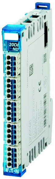
Digital input module, 20 digital inputs 24 V DC each, Negative switching, 5.0 ms
Digital I/O module with twenty 24 VDC / 3.7 mA (EN 61131-2 type 1) inputs with a 0.5 ms input filter.
| Function | XN300 I/O slice modules |
| Connection technique | Push-in spring-cage terminal |
| Function | XN-322 digital input module for XN300 |
| Short Description | 20 digital inputs 24 V DC each, negative switching, 5.0 ms |
| For use with | XN-312-… |
| Standards | |
| Approvals >Approvals |
IEC/EN 61131-2 IEC/EN 61000-6-2 IEC/EN 61000-6-4 |
| Approvals >shipping classification |
CE, cULus EAC |
| Approvals | DNV GL |
| Electromagnetic compatibility (EMC) >ESD [Air/contact discharge] |
|
| Electromagnetic compatibility (EMC) >Electromagnetic fields [(0.08…1) / (1,4…2) / (2…2,7) GHz ] |
8 / 4 kV |
| Electromagnetic compatibility (EMC) >Burst >Supply cable |
10 / 3 / 1 V/m |
| Electromagnetic compatibility (EMC) >Burst >Signal cable |
2 kV |
| Electromagnetic compatibility (EMC) >Surge >Supply cable (balanced / unbalanced) |
1 kV |
| Electromagnetic compatibility (EMC) >Surge >Signal cable (unbalanced) |
0,5 / 0,5 kV |
| Electromagnetic compatibility (EMC) >Radiated RFI |
1 kV |
| Electromagnetic compatibility (EMC) >Emitted interference (radiated, high frequency) [(30...230 MHz) / (230...1000 MHz)] |
10 V |
| Electromagnetic compatibility (EMC) >Voltage fluctuations/voltage dips |
40 / 47 class A dB |
| Ambient conditions >Climatic conditions >Climatic proofing |
Yes / 10 ms |
| Ambient conditions >Climatic conditions >Air pressure (operation) |
Dry heat to IEC 60068-2-2 Damp heat as per EN 60068-2-3 |
| Ambient conditions >Climatic conditions >Relative humidity |
795 - 1080 hPa |
| Ambient conditions >Climatic conditions >Condensation |
0 - 95%, non condensing |
| Ambient conditions >Temperature >Operation |
prevent with suitable measures |
| Ambient conditions >Temperature >Storage, transport [ϑ] |
0 - +60 °C |
| Degree of Protection | -20 - +85 °C |
| Mounting position | IP20 |
| Free fall, packaged (IEC/EN 60068-2-32) | Horizontal |
| Vibrations [3,5 mm / 1 g] | 1 m |
| Mechanical shock resistance [Semisinusoidal 15 g/11 ms] | 5 - 8.4 / 8.4 -150 Hz |
| Rated operational data >Insulating material group |
18 Impacts |
| Rated operational data >Overvoltage category / pollution degree |
|
| Rated operational data >Rated operating voltage |
I |
| Rated operational data >Maximum load current/cross-sectional area |
III / 3 |
| Connection design in TOP direction | 160 V |
| Stripping length | X (not specified by plug manufacturer) A / mm² |
| Gauge pin IEC/EN 60947-1 | Push-in spring-cage terminal (plug-in connection) |
| Connection specifications >"e" solid H07V-U |
10 mm |
| Connection specifications >"f" flexible H 07V-K |
A1 |
| Connection specifications >"f" with ferrules without plastic collar according to DIN 46228-1 (ferrules crimped gas-tight) |
0.2 - 1.5 mm2 |
| Connection specifications >"f" with ferrules with plastic collar according to DIN 46228-1 (ferrules crimped gas-tight) |
0.2 - 1.5 mm2 |
| Connection specifications >Cable size |
0.25 - 1.5 mm2 |
| Power supply - Input >Power supply >Current consumption for +5 V power supply (internal) [I] |
0.25-1,5 mm2 |
| Power supply - Input >Power supply >Current consumption for +24 V power supply [I] |
24 - 16 AWG |
| Power supply - Input >Power supply >Potential isolation [PE (polyethylene)] |
|
| Heat dissipation >Heat dissipation (without active channels) |
(typ.)35 mA |
| Heat dissipation >Max. heat dissipation |
(typ.)60 mA |
| Heat dissipation >Notes on heat dissipation |
no |
| Channels | 0.25 W |
| Input voltage >Nominal input voltage [Ue] |
2.49 W |
| Input voltage >Low level [UeL] |
The max. heat dissipation is specified as the maximum power produced inside the device´s housing. |
| Input voltage >High level [UeH] |
|
| Input current >Input current, nominal value [Ie] |
20 Number |
| Input current >Low level⁄active level [IeL] |
24 V DC |
| Input current >High level⁄active level [IeH] |
18 < UeL < +30 V |
| Input delay >tRising edge |
0 < UeH < +1 V |
| Input delay >tFalling edge |
3 mA |
| Potential isolation | ≤0.2 mA |
| Heat dissipation (per active channel) | ≥2.1 mA |
| Rated operational current for specified heat dissipation [In] | < 5000 µs |
| Heat dissipation per pole, current-dependent [Pvid] | < 5000 µs |
| Equipment heat dissipation, current-dependent [Pvid] | no Input to input |
| Static heat dissipation, non-current-dependent [Pvs] | 0.07 W |
| Heat dissipation capacity [Pdiss] | |
| Operating ambient temperature min. | 0 A |
| Operating ambient temperature max. | 0 W |
| Degree of Protection | 0 W |
| 10.2 Strength of materials and parts >10.2.2 Corrosion resistance |
2.49 W |
| 10.2 Strength of materials and parts >10.2.3.1 Verification of thermal stability of enclosures |
0 W |
| 10.2 Strength of materials and parts >10.2.3.2 Verification of resistance of insulating materials to normal heat |
0 °C |
| 10.2 Strength of materials and parts >10.2.3.3 Verification of resistance of insulating materials to abnormal heat and fire due to internal electric effects |
+55 °C |
| 10.2 Strength of materials and parts >10.2.4 Resistance to ultra-violet (UV) radiation |
IP20 |
| 10.2 Strength of materials and parts >10.2.5 Lifting |
|
| 10.2 Strength of materials and parts >10.2.6 Mechanical impact |
Meets the product standard´s requirements. |
| 10.2 Strength of materials and parts >10.2.7 Inscriptions |
Meets the product standard´s requirements. |
| 10.3 Degree of protection of ASSEMBLIES | Meets the product standard´s requirements. |
| 10.4 Clearances and creepage distances | Meets the product standard´s requirements. |
| 10.5 Protection against electric shock | Meets the product standard´s requirements. |
| 10.6 Incorporation of switching devices and components | Does not apply, since the entire switchgear needs to be evaluated. |
| 10.7 Internal electrical circuits and connections | Does not apply, since the entire switchgear needs to be evaluated. |
| 10.8 Connections for external conductors | Meets the product standard´s requirements. |
| 10.9 Insulation properties >10.9.2 Power-frequency electric strength |
Meets the product standard´s requirements. |
| 10.9 Insulation properties >10.9.3 Impulse withstand voltage |
Meets the product standard´s requirements. |
| 10.9 Insulation properties >10.9.4 Testing of enclosures made of insulating material |
Does not apply, since the entire switchgear needs to be evaluated. |
| 10.10 Temperature rise | Does not apply, since the entire switchgear needs to be evaluated. |
| 10.11 Short-circuit rating | Is the panel builder´s responsibility. |
| 10.12 Electromagnetic compatibility | Is the panel builder´s responsibility. |
| 10.13 Mechanical function | Is the panel builder´s responsibility. |
| Supply voltage AC 50 Hz | Is the panel builder´s responsibility. |
| Supply voltage AC 60 Hz | Is the panel builder´s responsibility. |
| Supply voltage DC | The panel builder is responsible for the temperature rise calculation. Eaton will provide heat dissipation data for the devices. |
| Voltage type of supply voltage | Is the panel builder´s responsibility. |
| Number of digital inputs | Is the panel builder´s responsibility. |
| Number of digital outputs | The device meets the requirements, provided the information in the instruction leaflet (IL) is observed. |
| Digital inputs configurable | |
| Digital outputs configurable | |
| Input current at signal 1 | 0 - 0 V |
| Permitted voltage at input | 0 - 0 V |
| Type of voltage (input voltage) | 18 - 30 V |
| Type of digital output | DC |
| Output current | 20 |
| Permitted voltage at output | 0 |
| Type of output voltage | No |
| Short-circuit protection, outputs available | No |
| Number of HW-interfaces industrial Ethernet | 2.1 mA |
| Number of interfaces PROFINET | 30 - 30 V |
| Number of HW-interfaces RS-232 | DC |
| Number of HW-interfaces RS-422 | None |
| Number of HW-interfaces RS-485 | 0 A |
| Number of HW-interfaces serial TTY | 0 - 0 V |
| Number of HW-interfaces parallel | DC |
| Number of HW-interfaces Wireless | No |
| Number of HW-interfaces USB | 0 |
| Number of HW-interfaces other | 0 |
| With optical interface | 0 |
| Supporting protocol for TCP/IP | 0 |
| Supporting protocol for PROFIBUS | 0 |
| Supporting protocol for CAN | 0 |
| Supporting protocol for INTERBUS | 0 |
| Supporting protocol for ASI | 0 |
| Supporting protocol for KNX | 0 |
| Supporting protocol for MODBUS | 1 |
| Supporting protocol for Data-Highway | No |
| Supporting protocol for DeviceNet | No |
| Supporting protocol for SUCONET | No |
| Supporting protocol for LON | Yes |
| Supporting protocol for PROFINET IO | No |
| Supporting protocol for PROFINET CBA | No |
| Supporting protocol for SERCOS | No |
| Supporting protocol for Foundation Fieldbus | No |
| Supporting protocol for EtherNet/IP | No |
| Supporting protocol for AS-Interface Safety at Work | No |
| Supporting protocol for DeviceNet Safety | No |
| Supporting protocol for INTERBUS-Safety | No |
| Supporting protocol for PROFIsafe | No |
| Supporting protocol for SafetyBUS p | No |
| Supporting protocol for other bus systems | No |
| Radio standard Bluetooth | No |
| Radio standard WLAN 802.11 | No |
| Radio standard GPRS | No |
| Radio standard GSM | No |
| Radio standard UMTS | No |
| IO link master | No |
| System accessory | No |
| Degree of protection (IP) | Yes |
| Type of electric connection | No |
| Time delay at signal exchange | No |
| Fieldbus connection over separate bus coupler possible | No |
| Rail mounting possible | No |
| Wall mounting/direct mounting | No |
| Front build in possible | No |
| Rack-assembly possible | Yes |
| Suitable for safety functions | IP20 |
| Category according to EN 954-1 | Screw-/spring clamp connection |
| SIL according to IEC 61508 | 0 - 5 ms |
| Performance level acc. EN ISO 13849-1 | No |
| Appendant operation agent (Ex ia) | Yes |
| Appendant operation agent (Ex ib) | No |
| Explosion safety category for gas | No |
| Explosion safety category for dust | No |
| Width | No |
| Height | None |
| Depth | None |
| Product Standards | None |
| UL File No. | No |
Tüm hakları saklıdır. Mnelko Endüstriyel San. ve Tic.Ltd.Şti. 2024