SKU: Eaton-140036
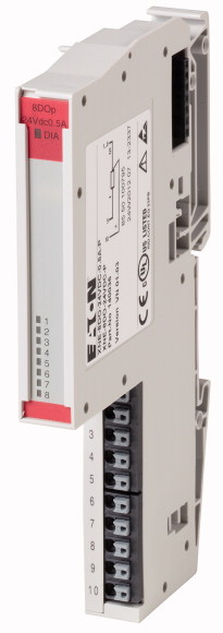
Digital output module XI/ON ECO, 24 V DC, 8DO
The XI/ON standard I/O system adds cost and space-optimized I/O modules and gateways to the XI/ON I/O system. The ECO modules do not need base modules and are fully compatible with the standard XI/ON system. High channel density (up to 16 DI/DO on 13 mm), push-in spring-cage terminals, 8 or 16 channels per module. The ECO gateways support the CANopen bus systems Profibus DP and Ethernet.
| Function | XI/ON I/O modules |
| Function | XNE Slice module |
| Short Description | 8 Digital output, 24 V DC/0.5 A Positive switching |
| Standards | |
| Potential isolation | EN 61000-6-2 EN 61000-6-4 EN 61131-2 |
| Ambient temperature >Ambient temperature, operation |
Yes, through optocoupler |
| Ambient temperature >Storage, transport [ϑ] |
0 - +55 °C |
| Relative humidity >Relative humidity |
-25 - +85 °C |
| Ambient conditions, mechanical >Degree of Protection |
5 - 95 % (indoor), Level RH-2, no condensation (for storage at 45°C) |
| Ambient conditions, mechanical >Harmful gases |
IP20 |
| Vibration resistance, operating conditions | SO2: 10 (rel. humidity < 75%, no condensation) H2S: 1.0 (rel. humidity < 75 %,no condensation) ppm |
| Mechanical shock resistance | according to IEC/EN 60068-2-6 |
| Continuous shock resistance (IEC/EN 60068-2-29) | according to IEC 60068-2-27 g |
| Drop and topple | According to IEC 60068-2-29 |
| Electromagnetic compatibility (EMC) >ESD [Air/contact discharge] |
According to IEC 60068-2-31, free fall according to IEC 60068-2-32 |
| Electromagnetic compatibility (EMC) >Electromagnetic fields [(0.08…1) / (1,4…2) / (2…2,7) GHz ] |
EN 61000-4-2 kV |
| Electromagnetic compatibility (EMC) >Burst |
EN 61100-4-2 V/m |
| Electromagnetic compatibility (EMC) >Surge |
EN 61100-4-4 |
| Electromagnetic compatibility (EMC) >Radiated RFI |
EN 61100-4-5 |
| Electromagnetic compatibility (EMC) >Emitted interference (radiated, high frequency) [(30...230 MHz) / (230...1000 MHz)] |
EN 61100-4-6 V |
| Electromagnetic compatibility (EMC) >Voltage fluctuations/voltage dips |
EN 55016-2-3 dB |
| Electromagnetic compatibility (EMC) >Type test |
EN 61131-2 |
| Approvals | to EN 61131-2 |
| Other technical data (sheet catalogue) | CE, cULus EAC |
| Rated data | Technical Data |
| Connection design in TOP direction | |
| Stripping length | according to VDE 0611 Part 1/8.92 / IEC/EN 60947-7-1 |
| Clamping range | Push-In spring-cage terminals |
| Connectable conductors >Outputs to EN 61131-2 |
8 mm |
| Connectable conductors >Reset after short-circuit rectified |
max. 0.14 - 1.5 mm2 |
| Connectable conductors >Vibration resistance, operating conditions |
0.25 - 1.5 mm2 |
| Connectable conductors >"f" with ferrules with plastic collar according to DIN 46228-1 (ferrules crimped gas-tight) |
0.25 - 1.5 mm2 |
| Connectable conductors >"e" solid H07V-U |
0.25 - 1.5 mm2 |
| Connectable conductors >"f" flexible H 07V-K |
0.25 - 0.75 mm2 |
| Connectable conductors >"f" with ferrules without plastic collar according to DIN 46228-1 (ferrules crimped gas-tight) |
0.25 - 1.5 mm2 |
| Connectable conductors >"f" with ferrules with plastic collar according to DIN 46228-1 (ferrules crimped gas-tight) |
0.25 - 1.5 mm2 |
| Gauge pin IEC/EN 60947-1 | 0.25 - 1.5 mm2 |
| Channels | 0.25 - 0.75 mm2 |
| Rated voltage through supply terminal [UL ] | A1 |
| Rated current consumption from supply terminal [IL ] | |
| Rated current consumption from module bus [IMB ] | 8 Number |
| Connectable sensors | 24 V DC |
| Channels | 3 mA |
| Rated voltage through supply terminal [UL ] | ≦ 15 mA |
| Rated current consumption from supply terminal [IL ] | Resistive loads Inductive loads Lamp loads |
| Rated current consumption from module bus [IMB ] | |
| Load resistance >Resistive load |
8 Number |
| Load resistance >Inductive load |
24 V DC |
| Channels | 3 mA |
| Rated voltage through supply terminal [UL ] | ≦ 15 mA |
| Rated current consumption from the supply terminal (at load current = 0 mA) [IL ] | ≧ 48 Ω |
| Rated current consumption from module bus [IMB ] | As per DC13 to IEC 60947-5-1 h |
| Power loss [P] | |
| Output voltage >High level [UH⁄UA ] |
8 Number |
| Output current >High level (rated value) [IH ] |
24 V DC |
| Output current >High level (permissible range) [IH ] |
3 mA |
| Delay on signal change and resistive load >from Low to High level |
≦ 15 mA |
| Delay on signal change and resistive load >From High to Low signal |
Normally 1.5 W |
| Utilization factor [%] | > UL - 1 V DC |
| Can be connected | 0.5 A |
| Resistive load | < 1.0 A |
| Inductive load | 300 µs |
| Lamp load [RLL ] | 300 µs |
| Switching frequency >With resistive load [f] |
100 g |
| Switching frequency >with inductive load |
Resistive loads Inductive loads Lamp loads |
| Switching frequency >Switching frequency with lamp load [f] |
≧ 48 Ω |
| Outputs to EN 61131-2 | As per DC13 to IEC 60947-5-1 h |
| Reset after short-circuit rectified [Ii ] | ≦ 6 W |
| Channels | 100 Hz |
| Rated voltage through supply terminal [UL ] | As per DC13 to IEC 60947-5-1 |
| Rated current consumption from supply terminal [IL ] | 10 Hz |
| Rated current consumption from module bus [IMB ] | short-circuit proof |
| Rated voltage through supply terminal [UL ] | Automatic |
| Rated current consumption from supply terminal [IL ] | |
| Rated current consumption from module bus [IMB ] | 8 Number |
| Power loss [P] | 24 V DC |
| Can be connected | 3 mA |
| Utilization factor [g] | ≦ 15 mA |
| Rated voltage through supply terminal [UL ] | |
| Rated current consumption from supply terminal [IL ] | 24 V DC |
| Rated current consumption from module bus [IMB ] | 3 mA |
| Power loss [P] | ≦ 15 mA |
| Channels | Normally 1.5 W |
| Rated voltage through supply terminal [UL ] | Resistive loads Inductive loads Lamp loads |
| Rated current consumption from supply terminal [IL ] | 100 % |
| Rated current consumption from module bus [IMB ] | |
| Output current >High level (permissible range) [IH ] |
24 V DC |
| Output current >High level (rated value) [IH ] |
3 mA |
| Switching frequency >Switching frequency with lamp load [f] |
≦ 15 mA |
| Lamp load [RLL ] | 1.5 W |
| Short-circuit rating | |
| Rated voltage through supply terminal [UL ] | 8 Number |
| Rated current consumption from supply terminal [IL ] | 24 V DC |
| Rated current consumption from module bus [IMB ] | 3 mA |
| Power loss [P] | ≦ 15 mA |
| Note for table header | |
| Rated operational current for specified heat dissipation [In] | < 1.0 A |
| Heat dissipation per pole, current-dependent [Pvid] | 0.5 A |
| Equipment heat dissipation, current-dependent [Pvid] | 10 Hz |
| Static heat dissipation, non-current-dependent [Pvs] | ≦ 6 W |
| Heat dissipation capacity [Pdiss] | short-circuit proof |
| Operating ambient temperature min. | |
| Operating ambient temperature max. | 24 V DC |
| Degree of Protection | 3 mA |
| 10.2 Strength of materials and parts >10.2.2 Corrosion resistance |
≦ 15 mA |
| 10.2 Strength of materials and parts >10.2.3.1 Verification of thermal stability of enclosures |
Normally 1.5 W |
| 10.2 Strength of materials and parts >10.2.3.2 Verification of resistance of insulating materials to normal heat |
|
| 10.2 Strength of materials and parts >10.2.3.3 Verification of resistance of insulating materials to abnormal heat and fire due to internal electric effects |
The supply terminal (UL) provides power for the module electronics and for the consumers at the outputs. The total current required for each module consists of the sum of all partial currents. Part of the XI/ON module’s electronics is supplied with module bus voltage (5 V DC), the other part through the supply terminal (UL). To increase the maximum output current to up to 1 A, two outputs can be connected in parallel. |
| 10.2 Strength of materials and parts >10.2.4 Resistance to ultra-violet (UV) radiation |
The rated current from supply terminal data apply at zero load current. Applies for resistive load: RLO < 1kΩ |
| 10.2 Strength of materials and parts >10.2.5 Lifting |
|
| 10.2 Strength of materials and parts >10.2.6 Mechanical impact |
0 A |
| 10.2 Strength of materials and parts >10.2.7 Inscriptions |
0 W |
| 10.3 Degree of protection of ASSEMBLIES | 0 W |
| 10.4 Clearances and creepage distances | 1.5 W |
| 10.5 Protection against electric shock | 0 W |
| 10.6 Incorporation of switching devices and components | 0 °C |
| 10.7 Internal electrical circuits and connections | +55 °C |
| 10.8 Connections for external conductors | IP20 |
| 10.9 Insulation properties >10.9.2 Power-frequency electric strength |
|
| 10.9 Insulation properties >10.9.3 Impulse withstand voltage |
Meets the product standard´s requirements. |
| 10.9 Insulation properties >10.9.4 Testing of enclosures made of insulating material |
Meets the product standard´s requirements. |
| 10.10 Temperature rise | Meets the product standard´s requirements. |
| 10.11 Short-circuit rating | Meets the product standard´s requirements. |
| 10.12 Electromagnetic compatibility | Meets the product standard´s requirements. |
| 10.13 Mechanical function | Does not apply, since the entire switchgear needs to be evaluated. |
| Supply voltage AC 50 Hz | Does not apply, since the entire switchgear needs to be evaluated. |
| Supply voltage AC 60 Hz | Meets the product standard´s requirements. |
| Supply voltage DC | Meets the product standard´s requirements. |
| Voltage type of supply voltage | Meets the product standard´s requirements. |
| Number of digital inputs | Does not apply, since the entire switchgear needs to be evaluated. |
| Number of digital outputs | Does not apply, since the entire switchgear needs to be evaluated. |
| Digital inputs configurable | Is the panel builder´s responsibility. |
| Digital outputs configurable | Is the panel builder´s responsibility. |
| Input current at signal 1 | Is the panel builder´s responsibility. |
| Permitted voltage at input | Is the panel builder´s responsibility. |
| Type of voltage (input voltage) | Is the panel builder´s responsibility. |
| Type of digital output | The panel builder is responsible for the temperature rise calculation. Eaton will provide heat dissipation data for the devices. |
| Output current | Is the panel builder´s responsibility. |
| Permitted voltage at output | Is the panel builder´s responsibility. |
| Type of output voltage | The device meets the requirements, provided the information in the instruction leaflet (IL) is observed. |
| Short-circuit protection, outputs available | |
| Number of HW-interfaces industrial Ethernet | |
| Number of interfaces PROFINET | 0 - 0 V |
| Number of HW-interfaces RS-232 | 0 - 0 V |
| Number of HW-interfaces RS-422 | 18 - 30 V |
| Number of HW-interfaces RS-485 | DC |
| Number of HW-interfaces serial TTY | 0 |
| Number of HW-interfaces parallel | 8 |
| Number of HW-interfaces Wireless | No |
| Number of HW-interfaces USB | No |
| Number of HW-interfaces other | 0 mA |
| With optical interface | 0 - 0 V |
| Supporting protocol for TCP/IP | DC |
| Supporting protocol for PROFIBUS | Other |
| Supporting protocol for CAN | 0.5 A |
| Supporting protocol for INTERBUS | 0 - 29 V |
| Supporting protocol for ASI | DC |
| Supporting protocol for KNX | Yes |
| Supporting protocol for MODBUS | 0 |
| Supporting protocol for Data-Highway | 0 |
| Supporting protocol for DeviceNet | 0 |
| Supporting protocol for SUCONET | 0 |
| Supporting protocol for LON | 0 |
| Supporting protocol for PROFINET IO | 0 |
| Supporting protocol for PROFINET CBA | 0 |
| Supporting protocol for SERCOS | 0 |
| Supporting protocol for Foundation Fieldbus | 0 |
| Supporting protocol for EtherNet/IP | 1 |
| Supporting protocol for AS-Interface Safety at Work | No |
| Supporting protocol for DeviceNet Safety | No |
| Supporting protocol for INTERBUS-Safety | Yes |
| Supporting protocol for PROFIsafe | Yes |
| Supporting protocol for SafetyBUS p | No |
| Supporting protocol for other bus systems | No |
| Radio standard Bluetooth | No |
| Radio standard WLAN 802.11 | No |
| Radio standard GPRS | No |
| Radio standard GSM | No |
| Radio standard UMTS | No |
| IO link master | No |
| System accessory | No |
| Degree of protection (IP) | No |
| Type of electric connection | No |
| Time delay at signal exchange | No |
| Fieldbus connection over separate bus coupler possible | No |
| Rail mounting possible | No |
| Wall mounting/direct mounting | No |
| Front build in possible | No |
| Rack-assembly possible | No |
| Suitable for safety functions | No |
| Category according to EN 954-1 | Yes |
| SIL according to IEC 61508 | No |
| Performance level acc. EN ISO 13849-1 | No |
| Appendant operation agent (Ex ia) | No |
| Appendant operation agent (Ex ib) | No |
| Explosion safety category for gas | No |
| Explosion safety category for dust | No |
| Width | Yes |
| Height | IP20 |
| Depth | Screw-/spring clamp connection |
| Product Standards | 0 - 0.3 ms |
| UL File No. | Yes |
| UL Category Control No. | Yes |
| CSA File No. | No |
| CSA Class No. | No |
| North America Certification | No |
| Specially designed for North America | No |
| Current Limiting Circuit-Breaker | None |
| Degree of Protection | None |
| Link to sheet catalogue | None |
Tüm hakları saklıdır. Mnelko Endüstriyel San. ve Tic.Ltd.Şti. 2024