SKU: Eaton-134921
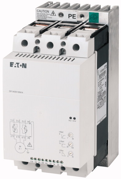
Soft starter, 135 A, 200 - 480 V AC, Us= 24 V AC/DC, Frame size FS4
Soft starter, Description: With internal bypass contacts, Function: Soft starters for three-phase loads, Mains supply voltage (50/60 Hz): ULN= 200 - 480 V AC, Supply voltage: Us= 24 V AC/DC, Control voltage: UC= 24 V AC, 24 V DC, Assigned motor rating (Standard connection, In-Line) at 400 V, 50 Hz: P= 75 kW, at 460 V, 60 Hz: P= 100 HP, Rated operational current AC-53: Ie= 135 A, Rated operational voltage: Ue= 200 V, 230 V, 400 V, 480 V, Connection to SmartWire-DT: no, Frame size: FS4, Standards: IEC/EN 60947-4-2, UL 508, CSA22.2-14
| Description | With internal bypass contacts |
| Function | Soft starters for three-phase loads |
| Mains supply voltage (50/60 Hz) [ULN] | 200 - 480 V AC |
| Supply voltage [Us] | 24 V AC/DC |
| Control voltage [UC] | 24 V AC 24 V DC |
| at 400 V, 50 Hz [P] | |
| at 460 V, 60 Hz [P] | 75 kW |
| AC-53 [Ie] | 100 HP |
| Rated operational voltage [Ue] | |
| Connection to SmartWire-DT | 135 A |
| Frame size | 200 V 230 V 400 V 480 V |
| Standards | no |
| Approvals | FS4 |
| Approvals | |
| Climatic proofing | IEC/EN 60947-4-2 UL 508 CSA22.2-14 |
| Ambient temperature >Operation [ϑ] |
CE |
| Ambient temperature >Storage [ϑ] |
UL CSA C-Tick UkrSEPRO |
| Altitude | Damp heat, constant, to IEC 60068-2-3 Damp heat, cyclic, to IEC 60068-2-10 |
| Mounting position | -5 - +40 up to 60 at 2% derating per Kelvin temperature rise °C |
| Degree of protection >Degree of Protection |
-25 - +60 °C |
| Degree of protection >Integrated |
0 - 1000 m, above that 1 % derating per 100 m , up to 2000 m m |
| Protection against direct contact | Vertical |
| Overvoltage category/pollution degree | IP20 (terminals IP00) |
| Shock resistance | Protection type IP40 can be achieved on all sides with covers from the NZM range. |
| Vibration resistance to EN 60721-3-2 | Finger- and back-of-hand proof |
| Radio interference level (IEC/EN 55011) | II/2 |
| Static heat dissipation, non-current-dependent [Pvs] | 8 g/11 ms |
| Weight | 2M2 |
| Rated operating voltage [Ue] | B |
| Supply frequency [fLN] | 24 W |
| Rated operational current [Ie
] >AC-53 [Ie] |
3.7 kg |
| Assigned motor rating (Standard connection, In-Line) >at 230 V, 50 Hz [P] |
|
| Assigned motor rating (Standard connection, In-Line) >at 400 V, 50 Hz [P] |
200 - 480 V AC |
| Assigned motor rating (Standard connection, In-Line) >at 200 V, 60 Hz [P] |
50/60 Hz |
| Assigned motor rating (Standard connection, In-Line) >at 230 V, 60 Hz [P] |
135 A |
| Assigned motor rating (Standard connection, In-Line) >at 460 V, 60 Hz [P] |
30 kW |
| Overload cycle to IEC/EN 60947-4-2 >AC-53a |
75 kW |
| Overload cycle to IEC/EN 60947-4-2 >Internal bypass contacts |
40 HP |
| Short-circuit rating >Type “1” coordination |
50 HP |
| Short-circuit rating >Type „2“ coordination (additional with the fuses for coordination type „1“) |
100 HP |
| Fuse base (number x part no.) | 135 A: AC-53a: 3 - 5: 75 - 10 |
| Cable lengths >Solid |
✓ |
| Cable lengths >Stranded |
NZMN2-M160 |
| Cable lengths >Solid or stranded |
3 x 170M4010 |
| Cable lengths >Copper band |
3 x 170H3004 |
| Cable lengths >Tightening torque |
|
| Cable lengths >Screwdriver (PZ: Pozidriv) |
1 x (4 - 185) 2 x (4 - 70) mm2 |
| Control cables >Solid |
1 x (4 - 185) 2 x (4 - 70) mm2 |
| Control cables >Flexible with ferrule |
1 x (12 - 350 kcmil) 2 x (12 - 00) AWG |
| Control cables >Stranded |
2 x 9 x 0.810 x 16 x 0.8 MM |
| Control cables >Solid or stranded |
5 (≤ 10 mm²); 14 (> 10 mm²) Nm |
| Control cables >Tightening torque |
PZ2; 1 x 6 mm mm |
| Control cables >Screwdriver |
1 x (0.5 - 2.5) 2 x (0.5 - 1.0) mm2 |
| Digital inputs >Control voltage >DC-operated |
1 x (0.5 - 1.5) 2 x (0.5 - 0.75) mm2 |
| Digital inputs >Control voltage >AC operated |
1 x (0.5 - 1.5) 2 x (0.5 - 1.0) mm2 |
| Digital inputs >Current consumption 24 V >External 24 V |
1 x (21 - 14) 2 x (21 - 18) AWG |
| Digital inputs >Pick-up voltage >DC-operated |
0.4 Nm |
| Digital inputs >Pick-up voltage >AC operated |
0,6 x 3,5 mm |
| Digital inputs >Drop-out voltage [x Us ] >DC operated |
|
| Digital inputs >Drop-out voltage [x Us ] >AC operated |
24 V DC +10 %/- 15 % V DC |
| Digital inputs >Pick-up time >DC operated |
24 V AC +10 %/- 15 % V AC |
| Digital inputs >Pick-up time >AC operated |
1.6 mA |
| Digital inputs >Drop-out time >DC operated |
17.3 - 27 V DC |
| Regulator supply >Voltage [Us] |
17.3 - 27 V AC |
| Regulator supply >Current consumption [Ie] |
0 - 3 V DC |
| Regulator supply >Current consumption at peak performance (close bypass) at 24 V DC [IPeak] |
0 - 3 V AC |
| Regulator supply >Notes |
250 ms |
| Relay outputs >Number |
250 ms |
| Relay outputs >Voltage range |
350 ms |
| Relay outputs >AC-11 current range |
24 V AC/DC +10 %/- 15 % V |
| Ramp times >Acceleration |
50 mA |
| Ramp times >Deceleration |
0,6/50 A/ms |
| Start voltage (= turn-off voltage) | External supply voltage |
| Start pedestal | 2 (TOR, Ready) |
| Fields of application >Fields of application |
250 V AC |
| Fields of application >1-phase motors |
1 A, AC-11 A |
| Fields of application >3-phase motors |
|
| Fast switching (semiconductor contactor) | 1 - 30 s |
| Soft start function | 0 - 30 s |
| Reversing starter | 30100 % |
| Suppression of closing transients | 30 - 100 % |
| Suppression of DC components for motors | Soft starting of three-phase asynchronous motors |
| Potential isolation between power and control sections | ● |
| Rated operational current for specified heat dissipation [In] | ✓ |
| Heat dissipation per pole, current-dependent [Pvid] | |
| Equipment heat dissipation, current-dependent [Pvid] | - (minimum ramp time 1s) |
| Static heat dissipation, non-current-dependent [Pvs] | ✓ |
| Heat dissipation capacity [Pdiss] | External solution required |
| Operating ambient temperature min. | ✓ |
| Operating ambient temperature max. | ✓ |
| 10.2 Strength of materials and parts >10.2.2 Corrosion resistance |
✓ |
| 10.2 Strength of materials and parts >10.2.3.1 Verification of thermal stability of enclosures |
|
| 10.2 Strength of materials and parts >10.2.3.2 Verification of resistance of insulating materials to normal heat |
Rated impulse withstand voltage:
|
| 10.2 Strength of materials and parts >10.2.3.3 Verification of resistance of insulating materials to abnormal heat and fire due to internal electric effects |
|
| 10.2 Strength of materials and parts >10.2.4 Resistance to ultra-violet (UV) radiation |
135 A |
| 10.2 Strength of materials and parts >10.2.5 Lifting |
0 W |
| 10.2 Strength of materials and parts >10.2.6 Mechanical impact |
24 W |
| 10.2 Strength of materials and parts >10.2.7 Inscriptions |
24 W |
| 10.3 Degree of protection of ASSEMBLIES | 0 W |
| 10.4 Clearances and creepage distances | -5 °C |
| 10.5 Protection against electric shock | +40 °C |
| 10.6 Incorporation of switching devices and components | |
| 10.7 Internal electrical circuits and connections | Meets the product standard´s requirements. |
| 10.8 Connections for external conductors | Meets the product standard´s requirements. |
| 10.9 Insulation properties >10.9.2 Power-frequency electric strength |
Meets the product standard´s requirements. |
| 10.9 Insulation properties >10.9.3 Impulse withstand voltage |
Meets the product standard´s requirements. |
| 10.9 Insulation properties >10.9.4 Testing of enclosures made of insulating material |
Meets the product standard´s requirements. |
| 10.10 Temperature rise | Does not apply, since the entire switchgear needs to be evaluated. |
| 10.11 Short-circuit rating | Does not apply, since the entire switchgear needs to be evaluated. |
| 10.12 Electromagnetic compatibility | Meets the product standard´s requirements. |
| 10.13 Mechanical function | Does not apply, since the entire switchgear needs to be evaluated. |
| Rated operation current Ie at 40 °C Tu | Meets the product standard´s requirements. |
| Rated operating voltage Ue | Does not apply, since the entire switchgear needs to be evaluated. |
| Rated power three-phase motor, inline, at 230 V | Does not apply, since the entire switchgear needs to be evaluated. |
| Rated power three-phase motor, inline, at 400 V | Is the panel builder´s responsibility. |
| Rated power three-phase motor, inside delta, at 230 V | Is the panel builder´s responsibility. |
| Rated power three-phase motor, inside delta, at 400 V | Is the panel builder´s responsibility. |
| Function | Is the panel builder´s responsibility. |
| Internal bypass | Is the panel builder´s responsibility. |
| With display | The panel builder is responsible for the temperature rise calculation. Eaton will provide heat dissipation data for the devices. |
| Torque control | Is the panel builder´s responsibility. The specifications for the switchgear must be observed. |
| Rated surrounding temperature without derating | Is the panel builder´s responsibility. The specifications for the switchgear must be observed. |
| Rated control supply voltage Us at AC 50HZ | The device meets the requirements, provided the information in the instruction leaflet (IL) is observed. |
| Rated control supply voltage Us at AC 60HZ | |
| Rated control supply voltage Us at DC | |
| Voltage type for actuating | 135 A |
| Integrated motor overload protection | 230 - 460 V |
| Release class | 30 kW |
| Degree of protection (IP) | 75 kW |
| Degree of protection (NEMA) | 0 kW |
| Product Standards | 0 kW |
| UL File No. | Single direction |
| CSA File No. | Yes |
| CSA Class No. | No |
| Specially designed for North America | No |
| Suitable for | 40 °C |
| Current Limiting Circuit-Breaker | 24 - 24 V |
| Max. Voltage Rating | 24 - 24 V |
| Degree of Protection | 24 - 24 V |
Tüm hakları saklıdır. Mnelko Endüstriyel San. ve Tic.Ltd.Şti. 2024