SKU: Eaton-120935
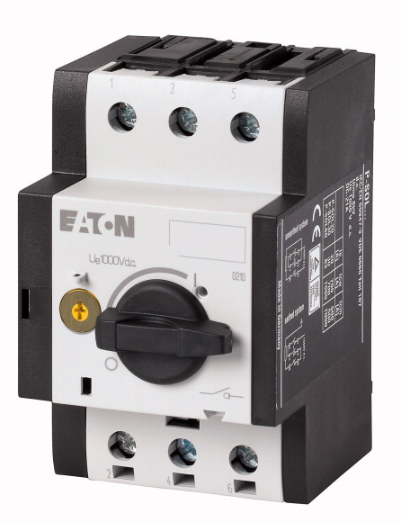
Switch-disconnector, DC current, 25A
Switch-disconnector, Standards: IEC/EN 60947-3, TÜV certificate, UL 508, CSA-C22.2 No. 14-10
| Product range | Switchgear for photovoltaic systems | ||||||||||||
| Subrange | DC switch-disconnectors | ||||||||||||
| Rated operational voltage [Ue] | 1000 V | ||||||||||||
| Protection class | 2 | ||||||||||||
| Number of conductors | 2 pole | ||||||||||||
| Rated operational current at DC-21A [Ie] | 25 A | ||||||||||||
| Rated operational current at DC-PV1 [Ie] | 25 A | ||||||||||||
| Design | open | ||||||||||||
| Notes |
|
||||||||||||
| Rated operational current at DC-21A [Ie] | 25 A | ||||||||||||
| Rated operational current at DC-PV1 [Ie] | 25 A | ||||||||||||
| Number of poles | 2 pole | ||||||||||||
| Rated operational voltage [Ue] | 1000 V | ||||||||||||
| Isolating characteristics | yes | ||||||||||||
| Standards | IEC/EN 60947-3 | ||||||||||||
| Lifespan, mechanical [Operations] | 100000 | ||||||||||||
| Electrical | 1500 Operations | ||||||||||||
| Max. operating frequency | 120 Ops/h | ||||||||||||
| Climatic proofing | Damp heat, constant, to IEC 60068-2-78 Damp heat, cyclic, to IEC 60068-2-30 |
||||||||||||
| Open | |||||||||||||
| Mounting position | -25 - +60 °C | ||||||||||||
| Width | As required | ||||||||||||
| Height | |||||||||||||
| Depth | 58 mm | ||||||||||||
| Top-hat rail | 93 mm | ||||||||||||
| Weight | 76 mm | ||||||||||||
| Flexible with ferrule | 35 mm | ||||||||||||
| Solid or stranded | 0.32 kg | ||||||||||||
| Rated short-time withstand current (t=1s) [Icw ] | |||||||||||||
| up to 440 V 50/60 Hz [Icm ] | 1 x (1 - 6) 2 x (1 - 6) mm2 |
||||||||||||
| Internal resistance | 18 - 14 AWG | ||||||||||||
| Rated operational current for specified heat dissipation [In] | 0.36 kA | ||||||||||||
| Heat dissipation per pole, current-dependent [Pvid] | 0.32 kA | ||||||||||||
| Equipment heat dissipation, current-dependent [Pvid] | 5 mΩ | ||||||||||||
| Static heat dissipation, non-current-dependent [Pvs] | |||||||||||||
| Heat dissipation capacity [Pdiss] | 25 A | ||||||||||||
| Operating ambient temperature min. | 1.5 W | ||||||||||||
| Operating ambient temperature max. | 4.5 W | ||||||||||||
| 10.2 Strength of materials and parts >10.2.2 Corrosion resistance |
0 W | ||||||||||||
| 10.2 Strength of materials and parts >10.2.3.1 Verification of thermal stability of enclosures |
0 W | ||||||||||||
| 10.2 Strength of materials and parts >10.2.3.2 Verification of resistance of insulating materials to normal heat |
-25 °C | ||||||||||||
| 10.2 Strength of materials and parts >10.2.3.3 Verification of resistance of insulating materials to abnormal heat and fire due to internal electric effects |
+60 °C | ||||||||||||
| 10.2 Strength of materials and parts >10.2.4 Resistance to ultra-violet (UV) radiation |
|||||||||||||
| 10.2 Strength of materials and parts >10.2.5 Lifting |
Meets the product standard´s requirements. | ||||||||||||
| 10.2 Strength of materials and parts >10.2.6 Mechanical impact |
Meets the product standard´s requirements. | ||||||||||||
| 10.2 Strength of materials and parts >10.2.7 Inscriptions |
Meets the product standard´s requirements. | ||||||||||||
| 10.3 Degree of protection of ASSEMBLIES | Meets the product standard´s requirements. | ||||||||||||
| 10.4 Clearances and creepage distances | Meets the product standard´s requirements. | ||||||||||||
| 10.5 Protection against electric shock | Does not apply, since the entire switchgear needs to be evaluated. | ||||||||||||
| 10.6 Incorporation of switching devices and components | Does not apply, since the entire switchgear needs to be evaluated. | ||||||||||||
| 10.7 Internal electrical circuits and connections | Meets the product standard´s requirements. | ||||||||||||
| 10.8 Connections for external conductors | Does not apply, since the entire switchgear needs to be evaluated. | ||||||||||||
| 10.9 Insulation properties >10.9.2 Power-frequency electric strength |
Meets the product standard´s requirements. | ||||||||||||
| 10.9 Insulation properties >10.9.3 Impulse withstand voltage |
Does not apply, since the entire switchgear needs to be evaluated. | ||||||||||||
| 10.9 Insulation properties >10.9.4 Testing of enclosures made of insulating material |
Does not apply, since the entire switchgear needs to be evaluated. | ||||||||||||
| 10.10 Temperature rise | Is the panel builder´s responsibility. | ||||||||||||
| 10.11 Short-circuit rating | Is the panel builder´s responsibility. | ||||||||||||
| 10.12 Electromagnetic compatibility | Is the panel builder´s responsibility. | ||||||||||||
| 10.13 Mechanical function | Is the panel builder´s responsibility. | ||||||||||||
| Version as main switch | Is the panel builder´s responsibility. | ||||||||||||
| Version as maintenance-/service switch | The panel builder is responsible for the temperature rise calculation. Eaton will provide heat dissipation data for the devices. | ||||||||||||
| Version as safety switch | Is the panel builder´s responsibility. The specifications for the switchgear must be observed. | ||||||||||||
| Version as emergency stop installation | Is the panel builder´s responsibility. The specifications for the switchgear must be observed. | ||||||||||||
| Version as reversing switch | The device meets the requirements, provided the information in the instruction leaflet (IL) is observed. | ||||||||||||
| Number of switches | |||||||||||||
| Max. rated operation voltage Ue AC | |||||||||||||
| Rated operating voltage | No | ||||||||||||
| Rated permanent current Iu | No | ||||||||||||
| Rated permanent current at AC-23, 400 V | No | ||||||||||||
| Rated permanent current at AC-21, 400 V | No | ||||||||||||
| Rated operation power at AC-3, 400 V | No | ||||||||||||
| Rated short-time withstand current lcw | 1 | ||||||||||||
| Rated operation power at AC-23, 400 V | 0 V | ||||||||||||
| Switching power at 400 V | 1000 - 1000 V | ||||||||||||
| Conditioned rated short-circuit current Iq | 30 A | ||||||||||||
| Number of poles | 0 A | ||||||||||||
| Number of auxiliary contacts as normally closed contact | 0 A | ||||||||||||
| Number of auxiliary contacts as normally open contact | 0 kW | ||||||||||||
| Number of auxiliary contacts as change-over contact | 0.36 kA | ||||||||||||
| Motor drive optional | 0 kW | ||||||||||||
| Motor drive integrated | 30 kW | ||||||||||||
| Voltage release optional | 0 kA | ||||||||||||
| Device construction | 2 | ||||||||||||
| Suitable for ground mounting | 0 | ||||||||||||
| Suitable for front mounting 4-hole | 0 | ||||||||||||
| Suitable for front mounting centre | 0 | ||||||||||||
| Suitable for distribution board installation | No | ||||||||||||
| Suitable for intermediate mounting | No | ||||||||||||
| Colour control element | Yes | ||||||||||||
| Type of control element | Built-in device fixed built-in technique | ||||||||||||
| Interlockable | Yes | ||||||||||||
| Type of electrical connection of main circuit | No | ||||||||||||
| Degree of protection (IP), front side | No | ||||||||||||
| Degree of protection (NEMA) | Yes | ||||||||||||
| Specially designed for North America | Yes | ||||||||||||
| Suitable for | Black |
Tüm hakları saklıdır. Mnelko Endüstriyel San. ve Tic.Ltd.Şti. 2024