SKU: Eaton-115444
DOL starter, 380 V 400 V 415 V: 0.12, 0.18 kW, Ir= 0.4 - 0.63 A, 110 V 50Hz/60Hz, AC
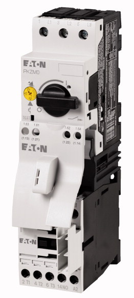
Premounted motor starter with minimized wiring time consisting of motor-protective circuit-breaker and contactor
| Basic function | DOL starters (complete devices) |
| Basic device | MSC |
| Notes | |
| Connection technique | Also suitable for motors with efficiency class IE3. IE3-ready devices are identified by the logo on their packaging. |
| Connection to SmartWire-DT | Screw terminals |
| Motor rating [P] >AC-3 >380 V 400 V 415 V [P] |
no |
| Rated operational current >AC-3 >380 V 400 V 415 V [Ie] |
|
| Setting range of overload releases |
0.12 0.18 kW |
| Coordination | 0.41 0.6 A |
| Contact sequence | |
| Actuating voltage | 0.4 - 0.63 A |
| Motor-protective circuit-breakers | Type of coordination “1” Type of coordination “2” |
| |
|
| DOL starter wiring set Mechanical connection element and electrical electric contact module |
110 V 50Hz/60Hz |
| Notes | AC |
| Standards | PKZM0-0,63 Type |
| Mounting position | DILM7-10(...) Part no. |
| Altitude | PKZM0-XDM12 Type |
| Ambient temperature | The DOL starter (complete device) consists of a PKZM0 motor protective circuit breaker and a DILM contactor. With the adapter-less top-hat rail mounting of starters up to 15 A, only the motor protective circuit breaker on the top-hat rail requires an adapter. The contactors are provided with mechanical support via a mechanical connection element. Control wire guide with max. 6 conductors up to 2.5°mm external diameter or 4 conductors up to 3.5°mm external diameter. From 16 A, the motor protective circuit breaker and contactor are mounted on the top hat rail adapter plate. The connection of the main circuit between PKZ and contactor is established with electrical contact modules. When using the auxiliary contacts DILA‐XHIT… (→ 101042) the plug-in electrical connector can be removed without the removal of the front mounting auxiliary contact. |
| Rated impulse withstand voltage [Uimp] | |
| Overvoltage category/pollution degree | IEC/EN 60947-4-1, VDE 0660 |
| Rated operational voltage [Ue] | |
| Rated operational current >Open, 3-pole: 50 – 60 Hz >380 V 400 V [Ie] |
Max. 2000 m |
| Motor protective circuit breaker PKZM0, PKE | -25 - +55 |
| DILM contactors >Current heat loss >Current heat loss at Ie to AC-3/400 V |
|
| DILM contactors >Power consumption of the coil in a cold state and 1.0 x US >Sealing power [Sealing] |
6000 V AC |
| Auxiliary contacts >Pilot Duty >AC operated |
III/3 |
| Auxiliary contacts >Pilot Duty >DC operated |
230 - 415 V |
| Auxiliary contacts >General Use >AC |
0.63 A |
| Auxiliary contacts >General Use >AC |
|
| Auxiliary contacts >General Use >DC |
PKZM0 motor-protective circuit-breakers, see motor-protective circuit-breakers/PKZM0 product group DILM contactors, see contactor product group DILET timing relay, ETR, see contactors, electronic timing relays product group |
| Auxiliary contacts >General Use >DC |
5.7 W |
| Rated operational current for specified heat dissipation [In] | 1.4 CO |
| Heat dissipation per pole, current-dependent [Pvid] | |
| Equipment heat dissipation, current-dependent [Pvid] | A600 |
| Static heat dissipation, non-current-dependent [Pvs] | P300 |
| Heat dissipation capacity [Pdiss] | 600 V |
| Operating ambient temperature min. | 15 A |
| Operating ambient temperature max. | 250 V |
| 10.2 Strength of materials and parts >10.2.2 Corrosion resistance |
1 A |
| 10.2 Strength of materials and parts >10.2.3.1 Verification of thermal stability of enclosures |
|
| 10.2 Strength of materials and parts >10.2.3.2 Verification of resistance of insulating materials to normal heat |
0.63 A |
| 10.2 Strength of materials and parts >10.2.3.3 Verification of resistance of insulating materials to abnormal heat and fire due to internal electric effects |
1.9 W |
| 10.2 Strength of materials and parts >10.2.4 Resistance to ultra-violet (UV) radiation |
5.7 W |
| 10.2 Strength of materials and parts >10.2.5 Lifting |
1.4 W |
| 10.2 Strength of materials and parts >10.2.6 Mechanical impact |
0 W |
| 10.2 Strength of materials and parts >10.2.7 Inscriptions |
-25 °C |
| 10.3 Degree of protection of ASSEMBLIES | +55 °C |
| 10.4 Clearances and creepage distances | |
| 10.5 Protection against electric shock | Meets the product standard´s requirements. |
| 10.6 Incorporation of switching devices and components | Meets the product standard´s requirements. |
| 10.7 Internal electrical circuits and connections | Meets the product standard´s requirements. |
| 10.8 Connections for external conductors | Meets the product standard´s requirements. |
| 10.9 Insulation properties >10.9.2 Power-frequency electric strength |
Meets the product standard´s requirements. |
| 10.9 Insulation properties >10.9.3 Impulse withstand voltage |
Does not apply, since the entire switchgear needs to be evaluated. |
| 10.9 Insulation properties >10.9.4 Testing of enclosures made of insulating material |
Does not apply, since the entire switchgear needs to be evaluated. |
| 10.10 Temperature rise | Meets the product standard´s requirements. |
| 10.11 Short-circuit rating | Does not apply, since the entire switchgear needs to be evaluated. |
| 10.12 Electromagnetic compatibility | Meets the product standard´s requirements. |
| 10.13 Mechanical function | Does not apply, since the entire switchgear needs to be evaluated. |
| Kind of motor starter | Does not apply, since the entire switchgear needs to be evaluated. |
| With short-circuit release | Is the panel builder´s responsibility. |
| Rated control supply voltage Us at AC 50HZ | Is the panel builder´s responsibility. |
| Rated control supply voltage Us at AC 60HZ | Is the panel builder´s responsibility. |
| Rated control supply voltage Us at DC | Is the panel builder´s responsibility. |
| Voltage type for actuating | Is the panel builder´s responsibility. |
| Rated operation power at AC-3, 230 V, 3-phase | The panel builder is responsible for the temperature rise calculation. Eaton will provide heat dissipation data for the devices. |
| Rated operation power at AC-3, 400 V | Is the panel builder´s responsibility. The specifications for the switchgear must be observed. |
| Rated power, 460 V, 60 Hz, 3-phase | Is the panel builder´s responsibility. The specifications for the switchgear must be observed. |
| Rated power, 575 V, 60 Hz, 3-phase | The device meets the requirements, provided the information in the instruction leaflet (IL) is observed. |
| Rated operation current Ie | |
| Rated operation current at AC-3, 400 V | |
| Overload release current setting | Direct starter |
| Rated conditional short-circuit current, type 1, 480 Y/277 V | Yes |
| Rated conditional short-circuit current, type 1, 600 Y/347 V | 110 - 110 V |
| Rated conditional short-circuit current, type 2, 230 V | 110 - 110 V |
| Rated conditional short-circuit current, type 2, 400 V | 0 - 0 V |
| Number of auxiliary contacts as normally open contact | AC |
| Number of auxiliary contacts as normally closed contact | 0.09 kW |
| Ambient temperature, upper operating limit | 0.18 kW |
| Temperature compensated overload protection | 0 kW |
| Release class | 0 kW |
| Type of electrical connection of main circuit | 0.6 A |
| Type of electrical connection for auxiliary- and control current circuit | 0.63 A |
| Rail mounting possible | 0.4 - 0.63 A |
| With transformer | 0 A |
| Number of command positions | 0 A |
| Suitable for emergency stop | 50000 A |
| Coordination class according to IEC 60947-4-3 | 50000 A |
| Number of indicator lights | 1 |
| External reset possible | 0 |
| With fuse | 60 °C |
| Degree of protection (IP) | Yes |
| Degree of protection (NEMA) | CLASS 10 |
| Supporting protocol for TCP/IP | Screw connection |
| Supporting protocol for PROFIBUS | Screw connection |
| Supporting protocol for CAN | Yes |
| Supporting protocol for INTERBUS | No |
| Supporting protocol for ASI | 0 |
| Supporting protocol for MODBUS | No |
| Supporting protocol for Data-Highway | Class 2 |
| Supporting protocol for DeviceNet | 0 |
| Supporting protocol for SUCONET | No |
| Supporting protocol for LON | No |
| Supporting protocol for PROFINET IO | IP20 |
| Supporting protocol for PROFINET CBA | Other |
| Supporting protocol for SERCOS | No |
| Supporting protocol for Foundation Fieldbus | No |
| Supporting protocol for EtherNet/IP | No |
| Supporting protocol for AS-Interface Safety at Work | No |
| Supporting protocol for DeviceNet Safety | No |
| Supporting protocol for INTERBUS-Safety | No |
| Supporting protocol for PROFIsafe | No |
| Supporting protocol for SafetyBUS p | No |
| Supporting protocol for other bus systems | No |
| Width | No |
| Height | No |
| Depth | No |
| Product Standards | No |
| UL File No. | No |
| UL Category Control No. | No |
| CSA File No. | No |
| CSA Class No. | No |
| North America Certification | No |
| Specially designed for North America | No |
Tüm hakları saklıdır. Mnelko Endüstriyel San. ve Tic.Ltd.Şti. 2024