SKU: Eaton-114297
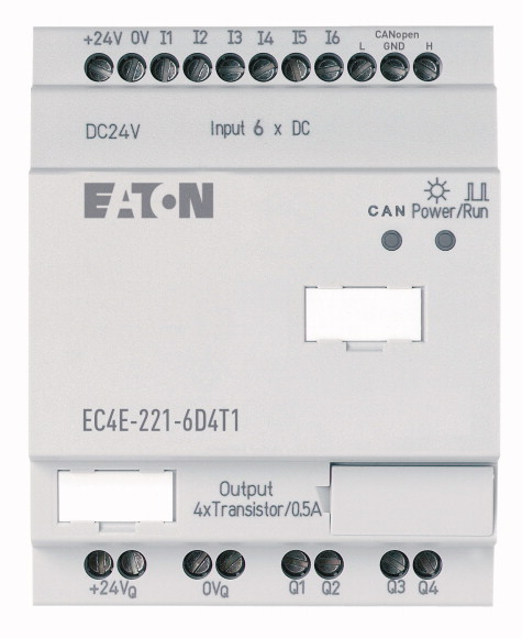
I/O expansion, integrated, 24 V DC, 6DI, 4DO(T)
I/O expansion via CANopen. Can be used for XC100/200, EC4P, XV-…
| Product range | Remote I/O systems Compact PLCs |
| Subrange | I/O expansions digital/analog |
| Basic function | Expansions |
| Description | usable via CANopen® |
| Function | CANopen® expansion EC4E |
| Inputs expansion (number) | |
| Transistor | Digital: 6 |
| Real time clock | |
| Supply voltage | 4 |
| For use with | |
| For use with | ✔ |
| Dimensions (W x H x D) | 24 V DC |
| Weight | easy800 EC4P MFD-CP8… MFD-CP10... |
| Mounting | XC100/200, EC4P, MFD4 (via CANopen®) |
| Solid | |
| Flexible with ferrule | 71.5 x 90 x 58 (4 PE) mm |
| Standard screwdriver | 0.2 kg |
| Max. tightening torque | Top-hat rail IEC/EN 60715, 35 mm or screw fixing using fixing brackets ZB4-101-GF1 (accessories) |
| Operating ambient temperature | |
| Condensation | 0.2/4 (AWG 22 - 12) mm2 |
| Storage [ϑ] | 0.2/2.5 (AWG 22 - 12) mm2 |
| Mounting position | 0.8 x 3.5 mm |
| Overvoltage category/pollution degree | 0.6 Nm |
| Electrostatic discharge (ESD) >applied standard |
|
| Electrostatic discharge (ESD) >Air discharge |
-25 to 55, cold as per IEC 60068-2-1, heat as per IEC 60068-2-2 °C |
| Electromagnetic fields (RFI) to IEC EN 61000-4-3 | Take appropriate measures to prevent condensation |
| Burst | -40 - +70 °C |
| power pulses (Surge) | |
| Immunity to line-conducted interference to (IEC/EN 61000-4-6) | Vertical or horizontal |
| Clearance in air and creepage distances | |
| Insulation resistance | II/2 |
| Rated operational voltage [Ue] | IEC EN 61000-4-2, Level 3 |
| Permissible range [Ue] | 8 kV |
| Residual ripple | 10 V/m |
| Input current | according to IEC/EN 61000-4-4 kV |
| Voltage dips | 2 kV (supply cables, symmetrical, EASY...AC) 0.5 kV (supply cables, symmetrical, easy-DC) according to IEC/EN 61000-4-5 |
| Heat dissipation [P] | 10 V |
| CANopen® >Data transfer rate |
|
| CANopen® >Bus termination (first and last station) |
EN 50178, UL 508, CSA C22.2, No. 142 |
| CANopen® >Connection types |
EN 50178 |
| Mode slave >Stations |
|
| Mode slave >PDO type |
24 DC (-15/+20%) V |
| Mode slave >Control contact rated current |
20.4 - 28.8 V DC |
| Number | ≦ 5 % |
| Potential isolation | 150 mA at Ue at no load |
| Rated operational voltage [Ue] | ≤ 20 (IEC/EN 61131-2) ms |
| Input voltage | Normally 3.5 W |
| Input current on 1 signal >Input current at signal 1 |
|
| Deceleration time | 500 kBit/s, 25 m250 kBit/s, 40m125 kBit/s, 125 m50 kBit/s, 300 m20 kBit/s, 700 m10 kBit/s, 1000 m |
| Cable length | Via integrated Dip switch |
| Number | 2 x terminals (see terminal capacity) |
| Rated operational voltage [Ue] | max. 62 Number |
| Permissible range [Ue] | Asynchronous, cyclic, acyclic |
| Residual ripple | to DS301V4 |
| Supply current | |
| Protection against polarity reversal | 6 |
| Potential isolation | from the outputs: yes |
| Rated operational current at signal „1” DC per channel [Ie] | 24 V DC |
| Lamp load without Rv per channel | < 5 (R1 - R6) at signal "0" > 15 (R1 - R6) at signal "1" V DC |
| Residual current on 0 signal per channel | 3.3 (R1 to R6 (R12)) mA |
| Max. output voltage | 20 (from “0” to “1”, debounce ON) Normally 0.25 (R1 - R12) (from “0” to “1”, debounce OFF) 20 (from „1“ to „0“) ms |
| Short-circuit protection | 100 (unshielded) m |
| Short-circuit tripping current for Ra ≦ 10 mΩ | |
| Total short-circuit current | 4 |
| Peak short-circuit current | 24 V DC |
| Thermal cutout | 20.4 - 28.8 V DC |
| Max. operating frequency with constant resistive load | 5 % |
| Parallel connection of outputs >With resistive load, inductive load with external suppressor circuit, combination within a group |
Norm./max. 9/16 at signal 0 12/22 at signal 1 mA |
| Parallel connection of outputs >Number of outputs [max.] |
yes (Caution: A short circuit will result if 0 V or earth is applied to the outputs in the event that the supply voltage is connected to the wrong poles.) |
| Parallel connection of outputs >Max. total current |
from power supply, inputs to the memory card: yes |
| Protection against polarity reversal | Max. 0.5 A |
| Bus termination (first and last station) | 5 W |
| Rated operational current for specified heat dissipation [In] | < 0.1 mA |
| Heat dissipation per pole, current-dependent [Pvid] | 2.5 (signal 0 at external load < 10 MΩ) U = Ue - 1 V (signal 1 at Ie = 0.5 A) V |
| Equipment heat dissipation, current-dependent [Pvid] | Yes, thermal (analysis via diagnostics input I16, I15; R15, R16) |
| Static heat dissipation, non-current-dependent [Pvs] | 0.7 ≦ Ie ≦ 2 per output A |
| Heat dissipation capacity [Pdiss] | 8 A |
| Operating ambient temperature min. | 16 A |
| Operating ambient temperature max. | Yes |
| 10.2 Strength of materials and parts >10.2.2 Corrosion resistance |
40000 Operations/h |
| 10.2 Strength of materials and parts >10.2.3.1 Verification of thermal stability of enclosures |
Group 1: Q1 to Q4 |
| 10.2 Strength of materials and parts >10.2.3.2 Verification of resistance of insulating materials to normal heat |
4 |
| 10.2 Strength of materials and parts >10.2.3.3 Verification of resistance of insulating materials to abnormal heat and fire due to internal electric effects |
2 (Caution! Outputs must be actuated simultaneously and for the same length of time.) A |
| 10.2 Strength of materials and parts >10.2.4 Resistance to ultra-violet (UV) radiation |
|
| 10.2 Strength of materials and parts >10.2.5 Lifting |
yes (Caution: A short circuit will result if 0 V or earth is applied to the outputs in the event that the supply voltage is connected to the wrong poles.) |
| 10.2 Strength of materials and parts >10.2.6 Mechanical impact |
|
| 10.2 Strength of materials and parts >10.2.7 Inscriptions |
Via integrated Dip switch |
| 10.3 Degree of protection of ASSEMBLIES | |
| 10.4 Clearances and creepage distances | 0 A |
| 10.5 Protection against electric shock | 0 W |
| 10.6 Incorporation of switching devices and components | 0 W |
| 10.7 Internal electrical circuits and connections | 3.4 W |
| 10.8 Connections for external conductors | 0 W |
| 10.9 Insulation properties >10.9.2 Power-frequency electric strength |
-25 °C |
| 10.9 Insulation properties >10.9.3 Impulse withstand voltage |
+55 °C |
| 10.9 Insulation properties >10.9.4 Testing of enclosures made of insulating material |
|
| 10.10 Temperature rise | Meets the product standard´s requirements. |
| 10.11 Short-circuit rating | Meets the product standard´s requirements. |
| 10.12 Electromagnetic compatibility | Meets the product standard´s requirements. |
| 10.13 Mechanical function | Meets the product standard´s requirements. |
| Supply voltage AC 50 Hz | Meets the product standard´s requirements. |
| Supply voltage AC 60 Hz | Does not apply, since the entire switchgear needs to be evaluated. |
| Supply voltage DC | Does not apply, since the entire switchgear needs to be evaluated. |
| Voltage type of supply voltage | Meets the product standard´s requirements. |
| Number of digital inputs | Meets the product standard´s requirements. |
| Number of digital outputs | Meets the product standard´s requirements. |
| Digital inputs configurable | Does not apply, since the entire switchgear needs to be evaluated. |
| Digital outputs configurable | Does not apply, since the entire switchgear needs to be evaluated. |
| Input current at signal 1 | Is the panel builder´s responsibility. |
| Permitted voltage at input | Is the panel builder´s responsibility. |
| Type of voltage (input voltage) | Is the panel builder´s responsibility. |
| Type of digital output | Is the panel builder´s responsibility. |
| Output current | Is the panel builder´s responsibility. |
| Permitted voltage at output | The panel builder is responsible for the temperature rise calculation. Eaton will provide heat dissipation data for the devices. |
| Type of output voltage | Is the panel builder´s responsibility. |
| Short-circuit protection, outputs available | Is the panel builder´s responsibility. |
| Redundancy | The device meets the requirements, provided the information in the instruction leaflet (IL) is observed. |
| Type of electric connection | |
| Time delay at signal exchange | |
| Suitable for safety functions | 0 - 0 V |
| Category according to EN 954-1 | 0 - 0 V |
| SIL according to IEC 61508 | 20.4 - 28.8 V |
| Performance level acc. EN ISO 13849-1 | DC |
| Appendant operation agent (Ex ia) | 6 |
| Appendant operation agent (Ex ib) | 4 |
| Explosion safety category for gas | No |
| Explosion safety category for dust | No |
| Width | 3.3 mA |
| Height | 0 - 0 V |
| Depth | DC |
| North America Certification | Transistor |
| Specially designed for North America | 0.5 A |
| Current Limiting Circuit-Breaker | 0 - 0 V |
| Degree of Protection | DC |
Tüm hakları saklıdır. Mnelko Endüstriyel San. ve Tic.Ltd.Şti. 2024