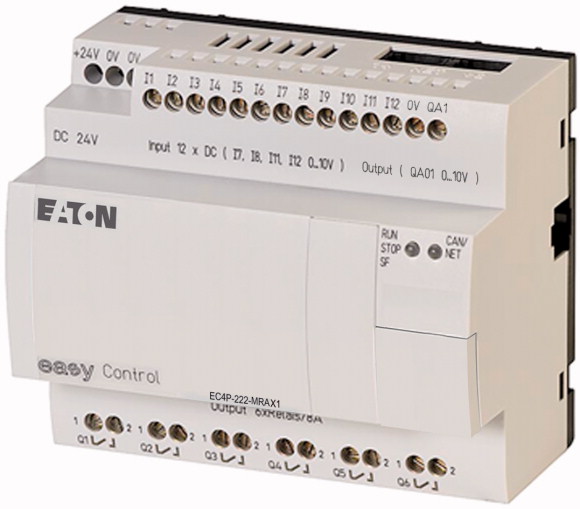
SKU: Eaton-106406
Compact PLC, 24 V DC, 12DI(of 4AI), 6DO(R), 1AO, ethernet, CAN
Compact controller for small and medium-sized automation tasks, programming according to IEC 61131 (CoDeSys), the Ethernet interface and the serial interface (ec4p-222 types) are for the purpose of programming, the communication via UDP and Modbus as well as connection of OPC clients
| Description | Expandable: Inputs/outputs and bus systems individual laser inscription possible with EC4-COMBINATION-* |
| Digital | easyNet/CANopen® and Ethernet on board |
| of which can be used as analog | |
| Relay 10 A (UL) | 12 |
| Analog | 4 |
| Supply voltage | |
| Dimensions (W x H x D) | 6 |
| Weight | 1 |
| Mounting | 24 V DC |
| Solid | |
| Flexible with ferrule | 107.5 x 90 x 72 without/79 with adapter for MCC (6 SU) mm |
| Standard screwdriver | 0.3 kg |
| Max. tightening torque | Top-hat rail IEC/EN 60715, 35 mm or screw fixing using 3 fixing brackets ZB4-101-GF1 (accessories) |
| Operating ambient temperature | |
| Condensation | 0.2/4 (AWG 22 - 12) mm2 |
| LCD display (clearly legible) | 0.2/2.5 (AWG 22 - 12) mm2 |
| Storage [ϑ] | 0.8 x 3.5 mm |
| Relative humidity, non-condensing (IEC/EN 60068-2-30) | 0.6 Nm |
| Air pressure (operation) | |
| Protection type (IEC/EN 60529, EN50178, VBG 4) | -25 to 55, cold as per IEC 60068-2-1, heat as per IEC 60068-2-2 °C |
| Vibrations (IEC/EN 60068-2-6) >Constant amplitude 0.15 mm |
Take appropriate measures to prevent condensation |
| Vibrations (IEC/EN 60068-2-6) >Constant acceleration 2 g |
0 - 55 °C |
| Mechanical shock resistance (IEC/EN 60068-2-27) semi-sinusoidal 15 g/11 ms | -40 - +70 °C |
| Drop to IEC/EN 60068-2-31 [Drop height] | 5 - 95 % |
| Free fall, packaged (IEC/EN 60068-2-32) | 1080 - 1080 hPa |
| Mounting position | |
| Overvoltage category/pollution degree | IP20 |
| Electrostatic discharge (ESD) >applied standard |
10 - 57 Hz |
| Electrostatic discharge (ESD) >Air discharge |
57 - 150 Hz |
| Electrostatic discharge (ESD) >Contact discharge |
18 Impacts |
| Electromagnetic fields (RFI) to IEC EN 61000-4-3 | 50 mm |
| Radio interference suppression | 1 m |
| Burst | Vertical or horizontal |
| Burst >Supply cable |
|
| Burst >Signal lines |
II/2 |
| power pulses (Surge) | IEC EN 61000-4-2, Level 3 |
| Immunity to line-conducted interference to (IEC/EN 61000-4-6) | 8 kV |
| Clearance in air and creepage distances | 6 kV |
| Insulation resistance | 10 V/m |
| Back-up of real-time clock | EN 55011 Class B, EN 55022 Class B |
| Accuracy of the real-time clock | IEC/EN 61000-4-4, level 3 kV |
| Write cycles of the retentive memory | 2 kV |
| Rated operational voltage [Ue] | 2 kV |
| Permissible range [Ue] | 2 kV (supply cables, symmetrical, EASY...AC) 0.5 kV (supply cables, symmetrical, easy-DC) according to IEC/EN 61000-4-5 |
| Residual ripple | 10 V |
| Input current | |
| Voltage dips | EN 50178, UL 508, CSA C22.2, No. 142 |
| Heat dissipation [P] | EN 50178 |
| Processor | |
| Memory >Program code/data |
|
| Memory >Marker/retentive data |
① Backup time (hours) with fully charged double layer capacitor ② Service life (years) |
| Cycle time for 1 k of instructions (Bit, Byte) | part no. ± 5 (± 0.5 h⁄Year) s/day |
| PRG interface RS232 >Data transfer rate |
|
| PRG interface RS232 >Connection types |
10000000000 (10¹⁰) (Read-write cycles) |
| PRG interface RS232 >Potential isolation |
|
| PRG interface RS232 >Master mode >Data transfer rate |
24 DC (-15/+20%) V |
| PRG interface RS232 >Master mode >Character formats |
20.4 - 28.8 V DC |
| PRG interface RS232 >Master mode >Number of transmission bytes in a block |
≦ 5 % |
| PRG interface RS232 >Master mode >Number of received bytes in a block |
normally 140 mA at Ue |
| Ethernet >Data transfer rate |
≤ 10 (IEC/EN 61131-2) ms |
| Ethernet >Connection types |
Normally 3.4 W |
| Ethernet >Potential isolation |
|
| CANopen® >Data transfer rate |
Infineon XC161 |
| CANopen® >Bus termination (first and last station) |
256/14 segments of 16 KB each kByte |
| CANopen® >Connection types |
16/4/4/8 KByte |
| Master mode >Number |
< 0.3 ms |
| Mode slave >Stations |
|
| Mode slave >PDO type |
4.8, 9.6, 19.2, 38.4, 57.6, 115.2 (character format: 8 bit data, no parity, 1 stop bit) kBit/s |
| Mode slave >Control contact rated current |
RJ45-bus |
| Number | none |
| Inputs can be used as analog inputs | 0.3, 0.6, 1.2, 2.4, 4.8, 9.6, 19.2, 38.4, 57.6 kbit/s |
| Status Display | 8E1, 8O1, 8N1, 8N2, 7E2, 7O2, 7N2, 7E1 |
| Potential isolation | 190 bytes |
| Rated operational voltage [Ue] | 190 bytes |
| Input voltage | 10 MBit/s, 100 m Mbit/s |
| Input current on 1 signal >Input current at signal 1 |
RJ45 |
| Deceleration time | No |
| Cable length | 500 kBit/s, 25 m 250 kBit/s, 60m 125 kBit/s, 125 m 50 kBit/s, 300 m 20 kBit/s, 700 m 10 kBit/s, 1000 m |
| Incremental counter >Number of counter inputs |
EASY-NT-R plug (incl. bus terminating resistor 120 Ω) |
| Incremental counter >Value range |
2 x RJ45, 8 pole |
| Incremental counter >Counter frequency |
8 |
| Incremental counter >Pulse shape |
max. 126 Number |
| Incremental counter >Counter inputs |
Asynchronous, cyclic, acyclic |
| Incremental counter >Reference input |
To DS 301 V4 |
| Incremental counter >Input for reference switch |
|
| Incremental counter >Counter inputs I1 and I2, I3 and I4 |
12 |
| Incremental counter >Signal offset |
4 (I7, I8, I11, I12) |
| Rapid counter inputs >Number |
LCD-Display |
| Rapid counter inputs >Value range |
from the outputs: yes to network easyNet, easyLink |
| Rapid counter inputs >Cable length |
24 V DC |
| Rapid counter inputs >Counter frequency |
< 5 (I1 - I6, I9 - I10) < 8 (I7, I8, I11, I12) at signal "0" > 15.0 (I1 - I6, I9, I10) > 8.0 (I7, I8, I11, I12) at signal "1" V DC |
| Rapid counter inputs >Pulse shape |
3.3 (I1 to I6) 2.2 (I7, I8) 3.3 (I9, I10) 2.2 (I11, I12) mA |
| Number | normally 0.02 (I1 - I4), normally 0.25 (I5 - I12) (from ´´0´´ to "1") normally 0.02 (I1 - I4), normally 0.25 (I5 - I12) (from ´´0´´ to "1") ms |
| Potential isolation | 100 (unshielded) m |
| Input type | 1 (I1, I2, I3, I4) |
| Signal range | 32 Bit |
| Resolution | ≦ 40 kHz |
| Input impedance | Square |
| Accuracy of actual value >Within a single device |
I1, I2 |
| Conversion time, analog/digital | I3 |
| Input current | I4 |
| Cable length | 1 |
| Number | 90° |
| Output type | 2 (I1, I2) at 16 Bit or 1 (I1) at 32 Bit |
| Max. output current | 16/32 Bit |
| Load resistance | ≦ 20 (screened) m |
| Overload and short-circuit protection | ≦ 50 kHz |
| Resolution | Square |
| Recovery time | |
| Accuracy >-25 °C - 55 °C |
4 (I7, I8, I11, I12) |
| Accuracy >25°C |
from the outputs: yes to interface/memory card: no |
| Conversion time, analog/digital | DC voltage |
| Outputs in groups of | 0-10 V DC |
| Parallel switching of outputs for increased output | 0.01 V analog 0.01 V digital 10 Bit (value 0 - 1023) |
| Protection of an output relay | 11.2 kΩ |
| Potential isolation | ± 2, (I7, I8, I11, I12) ± 0.12 V % |
| Lifespan, mechanical [Operations] | each CPU cycle ms |
| Contacts >Conventional thermal current (10 A UL) |
< 1 mA |
| Contacts >Recommended for load: 12 V AC/DC |
≦ 30, screened m |
| Contacts >Short-circuit-proof cos ϕ = 1, characteristic B16 at 600 A |
|
| Contacts >Short-circuit-proof cos ϕ = 0.5 to 0.7, characteristic B16 at 900 A |
1 |
| Contacts >Rated impulse withstand voltage Uimp of contact coil |
DC voltage |
| Contacts >Rated operational voltage [Ue] |
0.01 A |
| Rated insulation voltage [Ui] | 1 kΩ |
| Safe isolation according to EN 50178 | Yes |
| Making capacity >AC–-15, 250 V AC, 3 A (600 ops./h) [Operations] |
0.01 V DC analog 10 Bit (value 0 - 1023) digital |
| Making capacity >DC-13, L/R ≦ 150 ms, 24 V DC, 1 A (500 S/h) [Operations] |
100 µs |
| Breaking capacity >AC-15, 250 V AC, 3 A (600 Ops./h) [Operations] |
2 % |
| Breaking capacity >DC-13, L/R ≦ 150 ms, 24 V DC, 1 A (500 S/h) [Operations] |
1 % |
| Filament bulb load >1000 W at 230/240 V AC [Operations] |
each CPU cycle ms |
| Filament bulb load >500 W at 115/120 V AC [Operations] |
|
| Fluorescent lamp load >Fluorescent lamp load 10 x 58 W at 230/240 V AC >With upstream electrical device [Operations] |
1 |
| Fluorescent lamp load >Fluorescent lamp load 10 x 58 W at 230/240 V AC >Uncompensated [Operations] |
Not permissible |
| Fluorescent lamp load >Fluorescent lamp load 1 x 58 W at 230/240 V AC, conventional, compensated [Operations] |
Miniature circuit-breaker B16 or fuse 8 A (slow) |
| Switching frequency >Mechanical operations |
from power supply: yes From the inputs: yes in groups Safe isolation according to EN 50178: 300 V AC Basic isolation: 600 V AC |
| Switching frequency >Switching frequency |
10 x 106 |
| Switching frequency >Resistive load/lamp load |
8 A |
| Switching frequency >Inductive load |
> 500 mA |
| UL/CSA >Uninterrupted current at 240 V AC |
16 A |
| UL/CSA >Uninterrupted current at 24 V DC |
16 A |
| UL/CSA >AC >Control Circuit Rating Codes (utilization category) |
6 kV |
| UL/CSA >AC >Max. rated operational voltage |
250 V AC |
| UL/CSA >AC >max. thermal continuous current cos ϕ = 1 at B 300 |
250 V AC |
| UL/CSA >AC >max. make/break cos ϕ ≠ capacity 1 at B 300 |
300 between coil and contact 300 between two contacts V AC |
| UL/CSA >DC >Control Circuit Rating Codes (utilization category) |
300000 |
| UL/CSA >DC >Max. rated operational voltage |
200000 |
| UL/CSA >DC >Max. thermal uninterrupted current at R 300 |
300000 |
| UL/CSA >DC >Max. make/break capacity at R 300 |
200000 |
| Bus termination (first and last station) | 25000 |
| Rated operational current for specified heat dissipation [In] | 25000 |
| Heat dissipation per pole, current-dependent [Pvid] | 25000 |
| Equipment heat dissipation, current-dependent [Pvid] | 25000 |
| Static heat dissipation, non-current-dependent [Pvs] | 25000 |
| Heat dissipation capacity [Pdiss] | 10 x 106 |
| Operating ambient temperature min. | 10 Hz |
| Operating ambient temperature max. | 2 Hz |
| 10.2 Strength of materials and parts >10.2.2 Corrosion resistance |
0.5 Hz |
| 10.2 Strength of materials and parts >10.2.3.1 Verification of thermal stability of enclosures |
10 A |
| 10.2 Strength of materials and parts >10.2.3.2 Verification of resistance of insulating materials to normal heat |
8 A |
| 10.2 Strength of materials and parts >10.2.3.3 Verification of resistance of insulating materials to abnormal heat and fire due to internal electric effects |
B 300 Light Pilot Duty |
| 10.2 Strength of materials and parts >10.2.4 Resistance to ultra-violet (UV) radiation |
300 V AC |
| 10.2 Strength of materials and parts >10.2.5 Lifting |
5 A |
| 10.2 Strength of materials and parts >10.2.6 Mechanical impact |
3600/360 VA |
| 10.2 Strength of materials and parts >10.2.7 Inscriptions |
R 300 Light Pilot Duty |
| 10.3 Degree of protection of ASSEMBLIES | 300 V DC |
| 10.4 Clearances and creepage distances | 1 A |
| 10.5 Protection against electric shock | 28/28 VA |
| 10.6 Incorporation of switching devices and components | |
| 10.7 Internal electrical circuits and connections | EASY-NT-R plug (incl. bus terminating resistor 120 Ω) |
| 10.8 Connections for external conductors | |
| 10.9 Insulation properties >10.9.2 Power-frequency electric strength |
0 A |
| 10.9 Insulation properties >10.9.3 Impulse withstand voltage |
0 W |
| 10.9 Insulation properties >10.9.4 Testing of enclosures made of insulating material |
0 W |
| 10.10 Temperature rise | 3.4 W |
| 10.11 Short-circuit rating | 0 W |
| 10.12 Electromagnetic compatibility | -25 °C |
| 10.13 Mechanical function | +55 °C |
| Contains function building blocks | |
| Contains basic device | Meets the product standard´s requirements. |
| Contains module rack | Meets the product standard´s requirements. |
| Contains power supply | Meets the product standard´s requirements. |
| Contains analogue input module | Meets the product standard´s requirements. |
| Contains analogue output module | Meets the product standard´s requirements. |
| Contains digital input module | Does not apply, since the entire switchgear needs to be evaluated. |
| Contains digital output module | Does not apply, since the entire switchgear needs to be evaluated. |
| Contains function module | Meets the product standard´s requirements. |
| Contains technology module | Meets the product standard´s requirements. |
| Contains communication module | Meets the product standard´s requirements. |
| Contains memory unit | Does not apply, since the entire switchgear needs to be evaluated. |
| Contains simulation module | Does not apply, since the entire switchgear needs to be evaluated. |
| Contains connection cable | Is the panel builder´s responsibility. |
| Contains control unit | Is the panel builder´s responsibility. |
| Contains monitor | Is the panel builder´s responsibility. |
| Contains programming software | Is the panel builder´s responsibility. |
| Contains engineering software | Is the panel builder´s responsibility. |
| Contains visualization | The panel builder is responsible for the temperature rise calculation. Eaton will provide heat dissipation data for the devices. |
| Contains libraries | Is the panel builder´s responsibility. |
| Contains documentation | Is the panel builder´s responsibility. |
| Contains other components | The device meets the requirements, provided the information in the instruction leaflet (IL) is observed. |
| Software preinstalled | |
| Product Standards | |
| UL File No. | Yes |
| UL Category Control No. | Yes |
| CSA File No. | No |
| CSA Class No. | Yes |
| North America Certification | Yes |
| Specially designed for North America | Yes |
| Current Limiting Circuit-Breaker | Yes |
| Degree of Protection | Yes |
Tüm hakları saklıdır. Mnelko Endüstriyel San. ve Tic.Ltd.Şti. 2024