SKU: Eaton-102083
Miniature circuit breaker (MCB), 5A, 1p, C-Char, AC
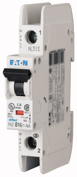
Miniature circuit breaker (MCB) FAZ-NA, 1 pole, Tripping characteristic: C, Rated current In: 5 A, Switchgear for export to North America (UL-listed)
| Basic function | Miniature circuit-breakers |
| Number of poles | 1 pole |
| Tripping characteristic | C |
| Application | Switchgear for export to North America (UL-listed) |
| Rated current [In] | 5 A |
| Rated switching capacity acc. to IEC/EN 60947-2 [Icu] | 15 kA |
| Product range | FAZ-NA |
| Standards | UL 489, CSA C22.2 No. 5 IEC 60947-2 |
| Rated operational voltage [Ue] [Ue] | 277/480 Y V AC |
| Rated operational voltage [Ue] | 60 V DC |
| Rated voltage according to IEC/EN 60947-2 [Un] | 254 V AC |
| Rated voltage according to UL [Un] | 277 V AC |
| Rated switching capacity acc. to IEC/EN 60947-2 [Icu] | 15 kA |
| Breaking capacity according to UL | 10 (UL489) kA |
| Characteristic | B, C, D |
| Selectivity Class | 3 |
| lifespan >Lifespan [Operations] |
> 20000 |
| Direction of incoming supply | as required |
| Standard front dimension | 45 mm |
| Enclosure height | 105 mm |
| Mounting width per pole | 17.7 mm |
| Mounting | IEC/EN 60715 top-hat rail |
| Degree of Protection | IP20, IP40 (when fitted) |
| Terminals top and bottom | Twin-purpose terminals |
| Terminal protection | Finger and back-of-hand proof to BGV A2 |
| Tightening torque of fixing screws | max. 2.4 UL: #18-12 AWG: 2.4 Nm (21 lb-in) #10-8 AWG: 2.8 Nm (25 lb-in) #6 AWG: 4 Nm (36 lb-in) N/m |
| Mounting position | As required |
| Rated operational current for specified heat dissipation [In] | 5 A |
| Heat dissipation per pole, current-dependent [Pvid] | 0 W |
| Equipment heat dissipation, current-dependent [Pvid] | 1.9 W |
| Static heat dissipation, non-current-dependent [Pvs] | 0 W |
| Heat dissipation capacity [Pdiss] | 0 W |
| Operating ambient temperature min. | -25 °C |
| Operating ambient temperature max. | +75 °C |
| 10.2 Strength of materials and parts >10.2.2 Corrosion resistance |
linear, per +1 °C, results in a 0.5% reduction of current carrying capacity |
| 10.2 Strength of materials and parts >10.2.3.1 Verification of thermal stability of enclosures |
Meets the product standard´s requirements. |
| 10.2 Strength of materials and parts >10.2.3.2 Verification of resistance of insulating materials to normal heat |
Meets the product standard´s requirements. |
| 10.2 Strength of materials and parts >10.2.3.3 Verification of resistance of insulating materials to abnormal heat and fire due to internal electric effects |
Meets the product standard´s requirements. |
| 10.2 Strength of materials and parts >10.2.4 Resistance to ultra-violet (UV) radiation |
Meets the product standard´s requirements. |
| 10.2 Strength of materials and parts >10.2.5 Lifting |
Meets the product standard´s requirements. |
| 10.2 Strength of materials and parts >10.2.6 Mechanical impact |
Does not apply, since the entire switchgear needs to be evaluated. |
| 10.2 Strength of materials and parts >10.2.7 Inscriptions |
Does not apply, since the entire switchgear needs to be evaluated. |
| 10.3 Degree of protection of ASSEMBLIES | Meets the product standard´s requirements. |
| 10.4 Clearances and creepage distances | Does not apply, since the entire switchgear needs to be evaluated. |
| 10.5 Protection against electric shock | Meets the product standard´s requirements. |
| 10.6 Incorporation of switching devices and components | Does not apply, since the entire switchgear needs to be evaluated. |
| 10.7 Internal electrical circuits and connections | Does not apply, since the entire switchgear needs to be evaluated. |
| 10.8 Connections for external conductors | Is the panel builder´s responsibility. |
| 10.9 Insulation properties >10.9.2 Power-frequency electric strength |
Is the panel builder´s responsibility. |
| 10.9 Insulation properties >10.9.3 Impulse withstand voltage |
Is the panel builder´s responsibility. |
| 10.9 Insulation properties >10.9.4 Testing of enclosures made of insulating material |
Is the panel builder´s responsibility. |
| 10.10 Temperature rise | Is the panel builder´s responsibility. |
| 10.11 Short-circuit rating | The panel builder is responsible for the temperature rise calculation. Eaton will provide heat dissipation data for the devices. |
| 10.12 Electromagnetic compatibility | Is the panel builder´s responsibility. The specifications for the switchgear must be observed. |
| 10.13 Mechanical function | Is the panel builder´s responsibility. The specifications for the switchgear must be observed. |
| Release characteristic | The device meets the requirements, provided the information in the instruction leaflet (IL) is observed. |
| Number of poles (total) | C |
| Number of protected poles | 1 |
| Rated current | 1 |
| Rated voltage | 5 A |
| Rated insulation voltage Ui | 240 V |
| Rated impulse withstand voltage Uimp | 440 V |
| Rated short-circuit breaking capacity Icn EN 60898 at 230 V | 4 kV |
| Rated short-circuit breaking capacity Icn EN 60898 at 400 V | 0 kA |
| Rated short-circuit breaking capacity Icu IEC 60947-2 at 230 V | 0 kA |
| Rated short-circuit breaking capacity Icu IEC 60947-2 at 400 V | 15 kA |
| Voltage type | 15 kA |
| Frequency | AC |
| Current limiting class | 50 - 60 Hz |
| Suitable for flush-mounted installation | 3 |
| Concurrently switching N-neutral | No |
| Over voltage category | No |
| Pollution degree | 3 |
| Additional equipment possible | 2 |
| Width in number of modular spacings | Yes |
| Built-in depth | 1 |
| Degree of protection (IP) | 70.5 mm |
| Ambient temperature during operating | IP20 |
| Connectable conductor cross section multi-wired | -25 - 75 °C |
| Connectable conductor cross section solid-core | 1 - 25 mm² |
| Product Standards | 1 - 25 mm² |
| UL File No. | IEC/EN 60947-2; UL 489; CSA-C22.2 No. 5-09; CE marking |
| UL Category Control No. | E235139 |
| CSA File No. | DIVQ |
| CSA Class No. | 204453 |
| North America Certification | 1432-01 |
| Specially designed for North America | UL listed, CSA certified |
| Suitable for | Yes, suitable as BCPD |
| Current Limiting Circuit-Breaker | Feeder circuits, branch circuits |
| Max. Voltage Rating | Yes |
| Degree of Protection | ≤ 32 A |
| Characteristic curve | IEC: IP20, UL/CSA Type: - |
| Characteristic curve |
Tüm hakları saklıdır. Mnelko Endüstriyel San. ve Tic.Ltd.Şti. 2024