SKU: Eaton-101050
Reversing starter, 380 V 400 V 415 V: 4 kW, Ir= 8 - 12 A, 230 V 50 Hz, 240 V 60 Hz, AC voltage
Reversing starter, Basic device: MSC, Notes: Also suitable for motors with efficiency class IE3., IE3-ready devices are identified by the logo on their packaging., Motor ratings Motor rating AC-3 380 V 400 V 415 V: P= 4 kW, Setting range of overload releases: Ir= 8 - 12 A, Coordination: Type of coordination “1”, Type of coordination “2”, Actuating voltage: 230 V 50 Hz, 240 V 60 Hz, AC voltage, Standards: UL 508 (on request), CSA C 22.2 No. 14 (on request)
| Basic function | Reversing starters (complete devices) | ||||||||||||
| Basic device | MSC | ||||||||||||
| Notes | |||||||||||||
| Connection technique | Also suitable for motors with efficiency class IE3. IE3-ready devices are identified by the logo on their packaging. |
||||||||||||
| Connection to SmartWire-DT | Screw terminals | ||||||||||||
| Motor rating [P] >AC-3 >380 V 400 V 415 V [P] |
no | ||||||||||||
| Rated operational current >AC-3 >380 V 400 V 415 V [Ie] |
|||||||||||||
| Rated short-circuit current 380 - 415 V [Iq ] | 4 kW | ||||||||||||
| Setting range of overload releases |
11.3 A | ||||||||||||
| Coordination | 50 kA | ||||||||||||
| Contact sequence | |||||||||||||
| Actuating voltage | 8 - 12 A | ||||||||||||
| Motor-protective circuit-breakers | Type of coordination “1” Type of coordination “2” |
||||||||||||
| |
|||||||||||||
| DOL starter wiring set Mechanical connection element and electrical electric contact module |
230 V 50 Hz, 240 V 60 Hz | ||||||||||||
| Notes | AC voltage | ||||||||||||
| Standards | PKZM0-12 Type | ||||||||||||
| Mounting position | DILM17-01(...) Part no. | ||||||||||||
| Altitude | PKZM0-XRM32 Type | ||||||||||||
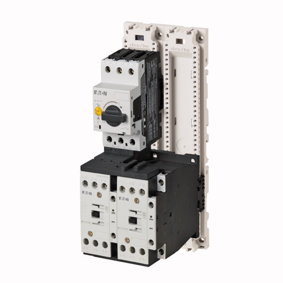
| Ambient temperature | The reversing starter (complete unit) consists of a PKZM0 motor-protective circuit-breaker and two DILM contactors. With the adapter-less top-hat rail mounting of starters up to 12 A, only the motor-protective circuit-breaker on the top-hat rail requires an adapter. The contactors are provided with mechanical support via a mechanical connection element. Control wire guide with max. 6 conductors up to 2.5mm external diameter or 4 conductors up to 3.5mm external diameter. From 16 A, the motor-protective circuit-breakers and contactors are mounted on the top-hat rail adapter plate. The connection of the main circuit between PKZ and contactor is established with electrical contact modules. Complete units with mechanical interlock, starters up to 12 A also feature electrical interlock. When using the auxiliary contacts DILA‐XHIT… (→ 101042) the plug-in electrical connector can be removed without the removal of the front mounting auxiliary contact.
|
||||||||||||
| Rated impulse withstand voltage [Uimp] | |||||||||||||
| Overvoltage category/pollution degree | UL 508 (on request) CSA C 22.2 No. 14 (on request) |
||||||||||||
| Rated operational voltage [Ue] | |||||||||||||
| Rated operational current >Open, 3-pole: 50 – 60 Hz >380 V 400 V [Ie] |
Max. 2000 m | ||||||||||||
| Motor protective circuit breaker PKZM0, PKE | -25 - +55 | ||||||||||||
| DILM contactors >Power consumption of the coil in a cold state and 1.0 x US >Dual-voltage coil 50 Hz [Sealing] |
|||||||||||||
| Auxiliary contacts >Pilot Duty >AC operated |
6000 V AC | ||||||||||||
| Auxiliary contacts >Pilot Duty >DC operated |
III/3 | ||||||||||||
| Auxiliary contacts >General Use >AC |
230 - 415 V | ||||||||||||
| Auxiliary contacts >General Use >AC |
12 A | ||||||||||||
| Auxiliary contacts >General Use >DC |
|||||||||||||
| Auxiliary contacts >General Use >DC |
PKZM0 motor-protective circuit-breakers, see motor-protective circuit-breakers/PKZM0 product group DILM contactors, see contactor product group DILET timing relay, ETR, see contactors, electronic timing relays product group |
||||||||||||
| Rated operational current for specified heat dissipation [In] | 2.1 W | ||||||||||||
| Heat dissipation per pole, current-dependent [Pvid] | |||||||||||||
| Equipment heat dissipation, current-dependent [Pvid] | A600 | ||||||||||||
| Static heat dissipation, non-current-dependent [Pvs] | P300 | ||||||||||||
| Heat dissipation capacity [Pdiss] | 600 V | ||||||||||||
| Operating ambient temperature min. | 15 A | ||||||||||||
| Operating ambient temperature max. | 250 V | ||||||||||||
| 10.2 Strength of materials and parts >10.2.2 Corrosion resistance |
1 A | ||||||||||||
| 10.2 Strength of materials and parts >10.2.3.1 Verification of thermal stability of enclosures |
|||||||||||||
| 10.2 Strength of materials and parts >10.2.3.2 Verification of resistance of insulating materials to normal heat |
12 A | ||||||||||||
| 10.2 Strength of materials and parts >10.2.3.3 Verification of resistance of insulating materials to abnormal heat and fire due to internal electric effects |
2.7 W | ||||||||||||
| 10.2 Strength of materials and parts >10.2.4 Resistance to ultra-violet (UV) radiation |
8.1 W | ||||||||||||
| 10.2 Strength of materials and parts >10.2.5 Lifting |
2.1 W | ||||||||||||
| 10.2 Strength of materials and parts >10.2.6 Mechanical impact |
0 W | ||||||||||||
| 10.2 Strength of materials and parts >10.2.7 Inscriptions |
-25 °C | ||||||||||||
| 10.3 Degree of protection of ASSEMBLIES | +55 °C | ||||||||||||
| 10.4 Clearances and creepage distances | |||||||||||||
| 10.5 Protection against electric shock | Meets the product standard´s requirements. | ||||||||||||
| 10.6 Incorporation of switching devices and components | Meets the product standard´s requirements. | ||||||||||||
| 10.7 Internal electrical circuits and connections | Meets the product standard´s requirements. | ||||||||||||
| 10.8 Connections for external conductors | Meets the product standard´s requirements. | ||||||||||||
| 10.9 Insulation properties >10.9.2 Power-frequency electric strength |
Meets the product standard´s requirements. | ||||||||||||
| 10.9 Insulation properties >10.9.3 Impulse withstand voltage |
Does not apply, since the entire switchgear needs to be evaluated. | ||||||||||||
| 10.9 Insulation properties >10.9.4 Testing of enclosures made of insulating material |
Does not apply, since the entire switchgear needs to be evaluated. | ||||||||||||
| 10.10 Temperature rise | Meets the product standard´s requirements. | ||||||||||||
| 10.11 Short-circuit rating | Does not apply, since the entire switchgear needs to be evaluated. | ||||||||||||
| 10.12 Electromagnetic compatibility | Meets the product standard´s requirements. | ||||||||||||
| 10.13 Mechanical function | Does not apply, since the entire switchgear needs to be evaluated. | ||||||||||||
| Kind of motor starter | Does not apply, since the entire switchgear needs to be evaluated. | ||||||||||||
| With short-circuit release | Is the panel builder´s responsibility. | ||||||||||||
| Rated control supply voltage Us at AC 50HZ | Is the panel builder´s responsibility. | ||||||||||||
| Rated control supply voltage Us at AC 60HZ | Is the panel builder´s responsibility. | ||||||||||||
| Rated control supply voltage Us at DC | Is the panel builder´s responsibility. | ||||||||||||
| Voltage type for actuating | Is the panel builder´s responsibility. | ||||||||||||
| Rated operation power at AC-3, 230 V, 3-phase | The panel builder is responsible for the temperature rise calculation. Eaton will provide heat dissipation data for the devices. | ||||||||||||
| Rated operation power at AC-3, 400 V | Is the panel builder´s responsibility. The specifications for the switchgear must be observed. | ||||||||||||
| Rated power, 460 V, 60 Hz, 3-phase | Is the panel builder´s responsibility. The specifications for the switchgear must be observed. | ||||||||||||
| Rated power, 575 V, 60 Hz, 3-phase | The device meets the requirements, provided the information in the instruction leaflet (IL) is observed. | ||||||||||||
| Rated operation current Ie | |||||||||||||
| Rated operation current at AC-3, 400 V | |||||||||||||
| Overload release current setting | Reversing starter | ||||||||||||
| Rated conditional short-circuit current, type 1, 480 Y/277 V | Yes | ||||||||||||
| Rated conditional short-circuit current, type 1, 600 Y/347 V | 230 - 230 V | ||||||||||||
| Rated conditional short-circuit current, type 2, 230 V | 0 - 0 V | ||||||||||||
| Rated conditional short-circuit current, type 2, 400 V | 0 - 0 V | ||||||||||||
| Number of auxiliary contacts as normally open contact | AC | ||||||||||||
| Number of auxiliary contacts as normally closed contact | 3 kW | ||||||||||||
| Ambient temperature, upper operating limit | 5.5 kW | ||||||||||||
| Temperature compensated overload protection | 0 kW | ||||||||||||
| Release class | 0 kW | ||||||||||||
| Type of electrical connection of main circuit | 11.3 A | ||||||||||||
| Type of electrical connection for auxiliary- and control current circuit | 12 A | ||||||||||||
| Rail mounting possible | 8 - 12 A | ||||||||||||
| With transformer | 0 A | ||||||||||||
| Number of command positions | 0 A | ||||||||||||
| Suitable for emergency stop | 50000 A | ||||||||||||
| Coordination class according to IEC 60947-4-3 | 50000 A | ||||||||||||
| Number of indicator lights | 0 | ||||||||||||
| External reset possible | 0 | ||||||||||||
| With fuse | 60 °C | ||||||||||||
| Degree of protection (IP) | Yes | ||||||||||||
| Degree of protection (NEMA) | CLASS 10 | ||||||||||||
| Supporting protocol for TCP/IP | Screw connection | ||||||||||||
| Supporting protocol for PROFIBUS | Screw connection | ||||||||||||
| Supporting protocol for CAN | Yes | ||||||||||||
| Supporting protocol for INTERBUS | No | ||||||||||||
| Supporting protocol for ASI | 0 | ||||||||||||
| Supporting protocol for MODBUS | No | ||||||||||||
| Supporting protocol for Data-Highway | Class 2 | ||||||||||||
| Supporting protocol for DeviceNet | 0 | ||||||||||||
| Supporting protocol for SUCONET | No | ||||||||||||
| Supporting protocol for LON | No | ||||||||||||
| Supporting protocol for PROFINET IO | IP00 | ||||||||||||
| Supporting protocol for PROFINET CBA | Other | ||||||||||||
| Supporting protocol for SERCOS | No | ||||||||||||
| Supporting protocol for Foundation Fieldbus | No | ||||||||||||
| Supporting protocol for EtherNet/IP | No | ||||||||||||
| Supporting protocol for AS-Interface Safety at Work | No | ||||||||||||
| Supporting protocol for DeviceNet Safety | No | ||||||||||||
| Supporting protocol for INTERBUS-Safety | No | ||||||||||||
| Supporting protocol for PROFIsafe | No | ||||||||||||
| Supporting protocol for SafetyBUS p | No | ||||||||||||
| Supporting protocol for other bus systems | No | ||||||||||||
| Width | No | ||||||||||||
| Height | No | ||||||||||||
| Depth | No | ||||||||||||
| Product Standards | No | ||||||||||||
| UL File No. | No | ||||||||||||
| UL Category Control No. | No | ||||||||||||
| CSA File No. | No | ||||||||||||
| CSA Class No. | No | ||||||||||||
| North America Certification | No | ||||||||||||
| Specially designed for North America | No |
Tüm hakları saklıdır. Mnelko Endüstriyel San. ve Tic.Ltd.Şti. 2024