SKU: Eaton-46988
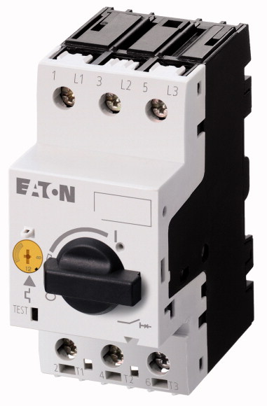
Motor-protective circuit-breaker, 9 kW, 16 - 20 A, Screw terminals
Motor-protective circuit-breaker according to IEC/EN60947, 3 pole size PKZM0, with adjustable overload and non-delayed short-circuit release, phase failure sensitive, screw and snap fitting, with screw terminal, cap installation dimension 45mm, rated operating voltage Ue 690V, degree of protection IP20, finger proof according to VDE 0106 T. 100, accessories: auxiliary contact, voltage release, contact module, clip plate
| Product range | PKZM0 motor protective circuit-breakers up to 32 A |
| Basic function | Motor protection |
| Notes | |
| Connection technique | Also suitable for motors with efficiency class IE3. IE3-ready devices are identified by the logo on their packaging. |
| Contact sequence | Screw terminals |
| AC-3 >220 V 230 V 240 V [P] |
|
| AC-3 >380 V 400 V 415 V [P] |
|
| AC-3 >440 V [P] |
5.5 kW |
| AC-3 >500 V [P] |
9 kW |
| AC-3 >660 V 690 V [P] |
11 kW |
| Rated uninterrupted current [Iu] | 12.5 kW |
| Overload releases |
15 kW |
| short-circuit release >max. [Irm ] |
20 A |
| Phase-failure sensitivity | |
| Explosion protection (according to ATEX 94/9/EC) | 16 - 20 A |
| Notes | 310 A |
| Standards | IEC/EN 60947-4-1, VDE 0660 Part 102 |
| Climatic proofing | PTB 10, ATEX 3013, Ex II(2) GD Observe manual MN03402003Z-DE/EN. |
| Ambient temperature >Storage |
Overload trigger: tripping class 10 A Can be snapped on to IEC/EN 60715 top-hat rail with 7.5 or 15 mm height. |
| Ambient temperature >Open |
|
| Ambient temperature >Enclosed |
IEC/EN 60947, VDE 0660,UL, CSA |
| Mounting position | Damp heat, constant, to IEC 60068-2-78 Damp heat, cyclic, to IEC 60068-2-30 |
| Direction of incoming supply | - 40 - 80 °C |
| Degree of protection >Device |
-25 - +55 °C |
| Degree of protection >Terminations |
- 25 - 40 °C |
| Protection against direct contact when actuated from front (EN 50274) | |
| Mechanical shock resistance half-sinusoidal shock 10 ms to IEC 60068-2-27 | as required |
| Altitude | IP20 |
| Terminal capacity main cable >Screw terminals >Solid |
IP00 |
| Terminal capacity main cable >Screw terminals >Flexible with ferrule to DIN 46228 |
Finger and back-of-hand proof |
| Terminal capacity main cable >Screw terminals >Solid or stranded |
25 g |
| Terminal capacity main cable >Screw terminals >Stripping length |
Max. 2000 m |
| Specified tightening torque for terminal screws >Main cable |
1 x (1 - 6) 2 x (1 - 6) mm2 |
| Specified tightening torque for terminal screws >Control circuit cables |
1 x (1 - 6) 2 x (1 - 6) mm2 |
| Rated impulse withstand voltage [Uimp] | 18 - 10 AWG |
| Overvoltage category/pollution degree | 10 mm |
| Rated operational voltage [Ue ] | 1.7 Nm |
| Rated uninterrupted current = rated operational current [Iu = Ie ] | 1 Nm |
| Rated frequency [f] | |
| Current heat loss (3 pole at operating temperature) | 6000 V AC |
| Impedance per pole | III/3 |
| Lifespan, mechanical [Operations] | 690 V AC |
| Lifespan, electrical (AC-3 at 400 V) >Lifespan, electrical [Operations] |
20 A |
| Max. operating frequency | 40 - 60 Hz |
| Short-circuit rating >DC >Short-circuit rating |
5.82 W |
| Short-circuit rating >DC >Notes |
5 mΩ |
| Motor switching capacity >AC-3 (up to 690V) |
0.1 x 10⁶ |
| Motor switching capacity >DC-5 (up to 250V) |
0.1 x 10⁶ |
| Temperature compensation >to IEC/EN 60947, VDE 0660 |
40 Ops/h |
| Temperature compensation >Operating range |
40 kA |
| Temperature compensation residual error for T > 40 °C | up to 250 V |
| Setting range of overload releases | 20 A |
| short-circuit release | 20 (3 contacts in series) A |
| Short-circuit release tolerance | |
| Phase-failure sensitivity | - 5…40 °C |
| Switching capacity >Maximum motor rating >Three-phase >200 V 208 V |
- 25…55 °C |
| Switching capacity >Maximum motor rating >Three-phase >575 V 600 V |
≦ 0.25 %/K |
| Switching capacity >Maximum motor rating >Single-phase >115 V 120 V |
0.6 - 1 x Iu |
| Switching capacity >Maximum motor rating >Single-phase >230 V 240 V |
Basic device, fixed: 15.5 x Iu |
| Short Circuit Current Rating, type E >240 V |
± 20% |
| Short Circuit Current Rating, type E >480 Y / 277 V |
IEC/EN 60947-4-1, VDE 0660 Part 102 |
| Short Circuit Current Rating, type E >Accessories required |
|
| Short Circuit Current Rating, group protection >600 V High Fault >SCCR (fuse) |
5 HP |
| Short Circuit Current Rating, group protection >600 V High Fault >max. Fuse |
15 HP |
| Short Circuit Current Rating, group protection >600 V High Fault >SCCR (CB) |
1.5 HP |
| Short Circuit Current Rating, group protection >600 V High Fault >max. CB |
3 HP |
| Short Circuit Current Rating, group protection >600 V High Fault >SCCR with CL (fuse) |
18 kA |
| Short Circuit Current Rating, group protection >600 V High Fault >max. Fuse (with CL) |
18 kA |
| Short Circuit Current Rating, group protection >600 V High Fault >SCCR with CL (CB) |
BK25/3-PKZ0-E |
| Short Circuit Current Rating, group protection >600 V High Fault >max. CB (with CL) |
10 kA |
| Rated operational current for specified heat dissipation [In] | 150 A |
| Heat dissipation per pole, current-dependent [Pvid] | 10 kA |
| Equipment heat dissipation, current-dependent [Pvid] | 125 A |
| Static heat dissipation, non-current-dependent [Pvs] | 18 A |
| Heat dissipation capacity [Pdiss] | 600 A |
| Operating ambient temperature min. | 18 kA |
| Operating ambient temperature max. | 600 A |
| 10.2 Strength of materials and parts >10.2.2 Corrosion resistance |
|
| 10.2 Strength of materials and parts >10.2.3.1 Verification of thermal stability of enclosures |
20 A |
| 10.2 Strength of materials and parts >10.2.3.2 Verification of resistance of insulating materials to normal heat |
1.94 W |
| 10.2 Strength of materials and parts >10.2.3.3 Verification of resistance of insulating materials to abnormal heat and fire due to internal electric effects |
5.82 W |
| 10.2 Strength of materials and parts >10.2.4 Resistance to ultra-violet (UV) radiation |
0 W |
| 10.2 Strength of materials and parts >10.2.5 Lifting |
0 W |
| 10.2 Strength of materials and parts >10.2.6 Mechanical impact |
-25 °C |
| 10.2 Strength of materials and parts >10.2.7 Inscriptions |
+55 °C |
| 10.3 Degree of protection of ASSEMBLIES | |
| 10.4 Clearances and creepage distances | Meets the product standard´s requirements. |
| 10.5 Protection against electric shock | Meets the product standard´s requirements. |
| 10.6 Incorporation of switching devices and components | Meets the product standard´s requirements. |
| 10.7 Internal electrical circuits and connections | Meets the product standard´s requirements. |
| 10.8 Connections for external conductors | Meets the product standard´s requirements. |
| 10.9 Insulation properties >10.9.2 Power-frequency electric strength |
Does not apply, since the entire switchgear needs to be evaluated. |
| 10.9 Insulation properties >10.9.3 Impulse withstand voltage |
Does not apply, since the entire switchgear needs to be evaluated. |
| 10.9 Insulation properties >10.9.4 Testing of enclosures made of insulating material |
Meets the product standard´s requirements. |
| 10.10 Temperature rise | Does not apply, since the entire switchgear needs to be evaluated. |
| 10.11 Short-circuit rating | Meets the product standard´s requirements. |
| 10.12 Electromagnetic compatibility | Does not apply, since the entire switchgear needs to be evaluated. |
| 10.13 Mechanical function | Does not apply, since the entire switchgear needs to be evaluated. |
| Overload release current setting | Is the panel builder´s responsibility. |
| Adjustment range undelayed short-circuit release | Is the panel builder´s responsibility. |
| With thermal protection | Is the panel builder´s responsibility. |
| Phase failure sensitive | Is the panel builder´s responsibility. |
| Switch off technique | Is the panel builder´s responsibility. |
| Rated operating voltage | The panel builder is responsible for the temperature rise calculation. Eaton will provide heat dissipation data for the devices. |
| Rated permanent current Iu | Is the panel builder´s responsibility. The specifications for the switchgear must be observed. |
| Rated operation power at AC-3, 230 V | Is the panel builder´s responsibility. The specifications for the switchgear must be observed. |
| Rated operation power at AC-3, 400 V | The device meets the requirements, provided the information in the instruction leaflet (IL) is observed. |
| Type of electrical connection of main circuit | |
| Type of control element | |
| Device construction | 20 - 20 A |
| With integrated auxiliary switch | 310 - 310 A |
| With integrated under voltage release | Yes |
| Number of poles | Yes |
| Rated short-circuit breaking capacity lcu at 400 V, AC | Thermomagnetic |
| Degree of protection (IP) | 690 - 690 V |
| Height | 20 A |
| Width | 5.5 kW |
| Depth | 9 kW |
| Product Standards | Screw connection |
| UL File No. | Turn button |
| UL Category Control No. | Built-in device fixed built-in technique |
| CSA File No. | No |
| CSA Class No. | No |
| North America Certification | 3 |
| Specially designed for North America | 50 kA |
| Suitable for | IP20 |
| Accessories | 93 mm |
| Characteristic curve | 45 mm |
| Characteristic curve | 76 mm |
| Characteristic curve | IEC/EN 60947-4-1; UL 60947-4-1; CSA - C22.2 No. 60947-4-1-14; CE marking |
Tüm hakları saklıdır. Mnelko Endüstriyel San. ve Tic.Ltd.Şti. 2024