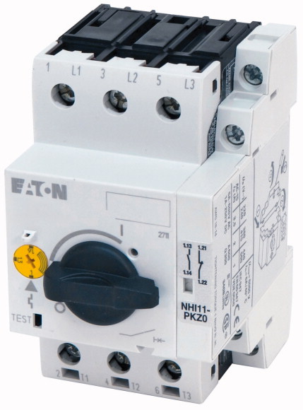
SKU: Eaton-39425
Motor-protective circuit-breaker, 3p+1N/O+1N/C, Ir=4-6.3A, screw connection
Motor-protective circuit-breaker with pre-assembled standard auxiliary contact as a complete device with assembly-related advantages due to shorter unpacking times
| Product range | PKZM0 motor protective circuit-breakers up to 32 A |
| Basic function | Motor protection |
| Notes | |
| Connection technique | Also suitable for motors with efficiency class IE3. IE3-ready devices are identified by the logo on their packaging. |
| AC-3 >220 V 230 V 240 V [P] |
Screw terminals |
| AC-3 >380 V 400 V 415 V [P] |
|
| AC-3 >440 V [P] |
1.1 kW |
| AC-3 >500 V [P] |
2.2 kW |
| AC-3 >660 V 690 V [P] |
3 kW |
| Rated uninterrupted current [Iu] | 3 kW |
| Overload releases |
4 kW |
| short-circuit release >max. [Irm ] |
6.3 A |
| Phase-failure sensitivity | |
| Explosion protection (according to ATEX 94/9/EC) | 4 - 6.3 A |
| Notes | 97.7 A |
| Standards | IEC/EN 60947-4-1, VDE 0660 Part 102 |
| Climatic proofing | PTB 10, ATEX 3013, Ex II(2) GD Observe manual MN03402003Z-DE/EN. |
| Ambient temperature >Storage |
Overload trigger: tripping class 10 A Can be snapped on to IEC/EN 60715 top-hat rail with 7.5 or 15 mm height. |
| Ambient temperature >Open |
|
| Ambient temperature >Enclosed |
IEC/EN 60947, VDE 0660,UL, CSA |
| Mounting position | Damp heat, constant, to IEC 60068-2-78 Damp heat, cyclic, to IEC 60068-2-30 |
| Direction of incoming supply | - 40 - 80 °C |
| Degree of protection >Device |
-25 - +55 °C |
| Degree of protection >Terminations |
- 25 - 40 °C |
| Protection against direct contact when actuated from front (EN 50274) | |
| Mechanical shock resistance half-sinusoidal shock 10 ms to IEC 60068-2-27 | as required |
| Altitude | IP20 |
| Terminal capacity main cable >Screw terminals >Solid |
IP00 |
| Terminal capacity main cable >Screw terminals >Flexible with ferrule to DIN 46228 |
Finger and back-of-hand proof |
| Terminal capacity main cable >Screw terminals >Solid or stranded |
25 g |
| Terminal capacity main cable >Screw terminals >Stripping length |
Max. 2000 m |
| Terminal capacity control circuit cables >Screw terminals >Solid |
1 x (1 - 6) 2 x (1 - 6) mm2 |
| Terminal capacity control circuit cables >Screw terminals >flexible with ferrules |
1 x (1 - 6) 2 x (1 - 6) mm2 |
| Terminal capacity control circuit cables >Screw terminals >Solid or stranded |
18 - 10 AWG |
| Specified tightening torque for terminal screws >Main cable |
10 mm |
| Specified tightening torque for terminal screws >Control circuit cables |
1 x (0.75…2.5) 2 x (0.75…2.5) mm2 |
| Rated impulse withstand voltage [Uimp] | 1 x (0.75…2.5) 2 x (0.75…2.5) mm2 |
| Overvoltage category/pollution degree | 18 - 14 AWG |
| Rated operational voltage [Ue ] | 1.7 Nm |
| Rated uninterrupted current = rated operational current [Iu = Ie ] | 1 Nm |
| Rated frequency [f] | |
| Current heat loss (3 pole at operating temperature) | 6000 V AC |
| Impedance per pole | III/3 |
| Lifespan, mechanical [Operations] | 690 V AC |
| Lifespan, electrical (AC-3 at 400 V) >Lifespan, electrical [Operations] |
6.3 A |
| Max. operating frequency | 40 - 60 Hz |
| Short-circuit rating >DC >Short-circuit rating |
5.68 W |
| Short-circuit rating >DC >Notes |
46 mΩ |
| Motor switching capacity >AC-3 (up to 690V) |
0.1 x 10⁶ |
| Motor switching capacity >DC-5 (up to 250V) |
0.1 x 10⁶ |
| Temperature compensation >to IEC/EN 60947, VDE 0660 |
40 Ops/h |
| Temperature compensation >Operating range |
60 kA |
| Temperature compensation residual error for T > 40 °C | up to 250 V |
| Setting range of overload releases | 6.3 A |
| short-circuit release | 6.3 (3 contacts in series) A |
| Short-circuit release tolerance | |
| Phase-failure sensitivity | - 5…40 °C |
| Switching capacity >Maximum motor rating >Three-phase >200 V 208 V |
- 25…55 °C |
| Switching capacity >Maximum motor rating >Three-phase >230 V 240 V |
≦ 0.25 %/K |
| Switching capacity >Maximum motor rating >Three-phase >460 V 480 V |
0.6 - 1 x Iu |
| Switching capacity >Maximum motor rating >Three-phase >575 V 600 V |
Basic device, fixed: 15.5 x Iu |
| Switching capacity >Maximum motor rating >Single-phase >115 V 120 V |
± 20% |
| Switching capacity >Maximum motor rating >Single-phase >230 V 240 V |
IEC/EN 60947-4-1, VDE 0660 Part 102 |
| Auxiliary contacts >Pilot Duty >AC operated |
|
| Auxiliary contacts >Pilot Duty >DC operated |
1 HP |
| Auxiliary contacts >General Use >AC |
1.5 HP |
| Auxiliary contacts >General Use >AC |
3 HP |
| Auxiliary contacts >General Use >DC |
5 HP |
| Auxiliary contacts >General Use >DC |
0.25 HP |
| Short Circuit Current Rating, type E >240 V |
0.5 HP |
| Short Circuit Current Rating, type E >480 Y / 277 V |
A600 |
| Short Circuit Current Rating, type E >600 Y / 347 V |
Q300 |
| Short Circuit Current Rating, type E >Accessories required |
600 V |
| Short Circuit Current Rating, group protection >600 V High Fault >SCCR (fuse) |
5 A |
| Short Circuit Current Rating, group protection >600 V High Fault >max. Fuse |
250 V |
| Short Circuit Current Rating, group protection >600 V High Fault >SCCR (CB) |
1 A |
| Short Circuit Current Rating, group protection >600 V High Fault >max. CB |
65 kA |
| Rated operational current for specified heat dissipation [In] | 65 kA |
| Heat dissipation per pole, current-dependent [Pvid] | 50 kA |
| Equipment heat dissipation, current-dependent [Pvid] | BK25/3-PKZ0-E |
| Static heat dissipation, non-current-dependent [Pvs] | 50 kA |
| Heat dissipation capacity [Pdiss] | 600 A |
| Operating ambient temperature min. | 50 kA |
| Operating ambient temperature max. | 600 A |
| 10.2 Strength of materials and parts >10.2.2 Corrosion resistance |
|
| 10.2 Strength of materials and parts >10.2.3.1 Verification of thermal stability of enclosures |
6.3 A |
| 10.2 Strength of materials and parts >10.2.3.2 Verification of resistance of insulating materials to normal heat |
1.89 W |
| 10.2 Strength of materials and parts >10.2.3.3 Verification of resistance of insulating materials to abnormal heat and fire due to internal electric effects |
5.68 W |
| 10.2 Strength of materials and parts >10.2.4 Resistance to ultra-violet (UV) radiation |
0 W |
| 10.2 Strength of materials and parts >10.2.5 Lifting |
0 W |
| 10.2 Strength of materials and parts >10.2.6 Mechanical impact |
-25 °C |
| 10.2 Strength of materials and parts >10.2.7 Inscriptions |
+55 °C |
| 10.3 Degree of protection of ASSEMBLIES | |
| 10.4 Clearances and creepage distances | Meets the product standard´s requirements. |
| 10.5 Protection against electric shock | Meets the product standard´s requirements. |
| 10.6 Incorporation of switching devices and components | Meets the product standard´s requirements. |
| 10.7 Internal electrical circuits and connections | Meets the product standard´s requirements. |
| 10.8 Connections for external conductors | Meets the product standard´s requirements. |
| 10.9 Insulation properties >10.9.2 Power-frequency electric strength |
Does not apply, since the entire switchgear needs to be evaluated. |
| 10.9 Insulation properties >10.9.3 Impulse withstand voltage |
Does not apply, since the entire switchgear needs to be evaluated. |
| 10.9 Insulation properties >10.9.4 Testing of enclosures made of insulating material |
Meets the product standard´s requirements. |
| 10.10 Temperature rise | Does not apply, since the entire switchgear needs to be evaluated. |
| 10.11 Short-circuit rating | Meets the product standard´s requirements. |
| 10.12 Electromagnetic compatibility | Does not apply, since the entire switchgear needs to be evaluated. |
| 10.13 Mechanical function | Does not apply, since the entire switchgear needs to be evaluated. |
| Overload release current setting | Is the panel builder´s responsibility. |
| Adjustment range undelayed short-circuit release | Is the panel builder´s responsibility. |
| With thermal protection | Is the panel builder´s responsibility. |
| Phase failure sensitive | Is the panel builder´s responsibility. |
| Switch off technique | Is the panel builder´s responsibility. |
| Rated operating voltage | The panel builder is responsible for the temperature rise calculation. Eaton will provide heat dissipation data for the devices. |
| Rated permanent current Iu | Is the panel builder´s responsibility. The specifications for the switchgear must be observed. |
| Rated operation power at AC-3, 230 V | Is the panel builder´s responsibility. The specifications for the switchgear must be observed. |
| Rated operation power at AC-3, 400 V | The device meets the requirements, provided the information in the instruction leaflet (IL) is observed. |
| Type of electrical connection of main circuit | |
| Type of control element | |
| Device construction | 4 - 6.3 A |
| With integrated auxiliary switch | 98 - 98 A |
| With integrated under voltage release | Yes |
| Number of poles | Yes |
| Rated short-circuit breaking capacity lcu at 400 V, AC | Thermomagnetic |
| Degree of protection (IP) | 690 - 690 V |
| Height | 6.3 A |
| Width | 1.1 kW |
| Depth | 2.2 kW |
| Product Standards | Screw connection |
| UL File No. | Turn button |
| UL Category Control No. | Built-in device fixed built-in technique |
| CSA File No. | Yes |
| CSA Class No. | No |
| North America Certification | 3 |
| Specially designed for North America | 150 kA |
| Suitable for | IP20 |
| Accessories | 93 mm |
| Characteristic curve | 54 mm |
| Characteristic curve | 76 mm |
| Characteristic curve | IEC/EN 60947-4-1; UL 60947-4-1; CSA - C22.2 No. 60947-4-1-14; CE marking |
Tüm hakları saklıdır. Mnelko Endüstriyel San. ve Tic.Ltd.Şti. 2024