SKU: Eaton-2397
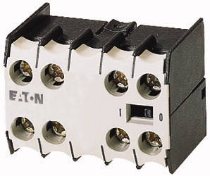
Auxiliary contact module, 4 pole, 1 N/O, 3 NC, Front fixing, Screw terminals, DILE(E)M, DILER
Auxiliary contact module, with interlocked opposing contacts, Switching elements according to EN 50005, Switching elements according to EN 50012 are to be preferred., Version E combinations correspond to EN 50011 and are to be preferred., Function: for standard applications, 4 pole, Connection technique: Screw terminals, Rated operational current AC-15 220 V 230 V 240 V: Ie= 4 A, Rated operational current AC-15 380 V 400 V 415 V: Ie= 2 A, Contacts N/O = Normally open: 1 N/O, Contacts N/C = Normally closed: 3 NC, Mounting type: Front fixing, For use with: DILEM-10(-G)(…), DILEM-01(-G)(…), DILEM-4(-G)(…), DILER40(-G), DILER31(-G), DILER22, DILEEM-10(-G)(…), DILEEM-01(-G)(…), DILEM12-10(-G)(…), DILEM12-01(-G)(…), Instructions: Interlocked opposing contacts according to IEC/EN 60947-5-1 appendix L, inside the auxiliary contact modules, also for the integrated auxiliary contacts of the DILE(E)M, Auxiliary contacts used as mirror contacts according to IEC/EN 60947-4-1 Appendix F (not N/C late open), Code number and version of combination Distinctive number: 53E, 44, 35
| Accessories | Auxiliary contact modules |
| Description | with interlocked opposing contacts Switching elements according to EN 50005 Switching elements according to EN 50012 are to be preferred. Version E combinations correspond to EN 50011 and are to be preferred. |
| Function | for standard applications |
| Number of poles | 4 pole |
| Connection technique | Screw terminals |
| AC-15 >220 V 230 V 240 V [Ie] |
|
| AC-15 >380 V 400 V 415 V [Ie] |
4 A |
| N/O = Normally open | 2 A |
| N/C = Normally closed | |
| Mounting type | 1 N/O |
| Contact sequence | 3 NC |
| For use with | Front fixing |
| Instructions | |
| Distinctive number | DILEM-10(-G)(…) DILEM-01(-G)(…) DILEM-4(-G)(…) DILER40(-G) DILER31(-G) DILER22 DILEEM-10(-G)(…) DILEEM-01(-G)(…) DILEM12-10(-G)(…) DILEM12-01(-G)(…) |
| with basic device | Interlocked opposing contacts according to IEC/EN 60947-5-1 appendix L, inside the auxiliary contact modules, also for the integrated auxiliary contacts of the DILE(E)M Auxiliary contacts used as mirror contacts according to IEC/EN 60947-4-1 Appendix F (not N/C late open) |
| with basic device | |
| with basic device | 53E |
| Standards | DILER-40(-G) |
| Lifespan, mechanical >AC operated [Operations] |
44 |
| Lifespan, mechanical >DC operated [Operations] |
DILER-31(-G) |
| Component lifespan at Ue = 240 V >AC-15 [Operations] |
35 |
| Component lifespan at Ue = 240 V >DC >L/R = 50 ms: 2 contacts in series at Ie = 0.5 A [Operations] |
DILER-22 |
| Maximum operating frequency [Operations/h] | |
| Climatic proofing | IEC/EN 60947, VDE 0660, UL, CSA |
| Ambient temperature >Open |
10 x 106 |
| Ambient temperature >Enclosed |
20 x 106 |
| Ambient temperature >Ambient temperature, storage |
0.2 x 10⁶ |
| Mounting position >Mounting position |
0.15 x 10⁶ |
| Mechanical shock resistance (IEC/EN 60068-2-27) >Half-sinusoidal shock, 10 ms >Basic unit with auxiliary contact module >N/O contact |
9000 |
| Mechanical shock resistance (IEC/EN 60068-2-27) >Half-sinusoidal shock, 10 ms >Basic unit with auxiliary contact module >N/C contact |
Damp heat, constant, to IEC 60068-2-78 Damp heat, cyclic, to IEC 60068-2-30 |
| Degree of Protection | -25 - +50 °C |
| Protection against direct contact when actuated from front (EN 50274) | - 25 - 40 °C |
| Weight | - 40 - 80 °C |
| Terminal capacities >Screw terminals >Solid |
As required, except vertical with terminals A1/A2 at the bottom |
| Terminal capacities >Screw terminals >Flexible with ferrule |
10 g |
| Terminal capacities >Screw terminals >Solid or stranded |
8 g |
| Terminal capacities >Screw terminals >Terminal screw |
IP20 |
| Terminal capacities >Screw terminals >Pozidriv screwdriver |
Finger and back-of-hand proof |
| Terminal capacities >Screw terminals >Standard screwdriver |
0.04 kg |
| Terminal capacities >Screw terminals >Max. tightening torque |
1 x (0.75 - 2.5) 2 x (0.75 - 2.5) mm2 |
| Interlocked opposing contacts within an auxiliary contact module (to IEC 60947-5-1 Annex L) | 1 x (0.75 - 1.5) 2 x (0.75 - 1.5) mm2 |
| Rated impulse withstand voltage [Uimp] | Single 18 – 14/Double 18 – 14 AWG |
| Overvoltage category/pollution degree | M3.5 |
| Rated insulation voltage [Ui] | 2 Size |
| Rated operational voltage [Ue] | 0.8 x 5.5 1 x 6 mm |
| Safe isolation to EN 61140 >between coil and auxiliary contacts |
1.2 Nm |
| Safe isolation to EN 61140 >between the auxiliary contacts |
|
| Rated operational current >Conventional free air thermal current, 1 pole >Notes |
Yes |
| Rated operational current >Conventional free air thermal current, 1 pole >Conv. thermal current [Ith] |
6000 V AC |
| Rated operational current >AC-15 >220 V 230 V 240 V [Ie] |
III/3 |
| Rated operational current >AC-15 >380 V 400 V 415 V [Ie] |
690 V AC |
| Rated operational current >AC-15 >500 V [Ie] |
600 V AC |
| Rated operational current >DC current |
300 V AC |
| Rated operational current >DC current >DC L/R ≦ 15 ms >Contacts in series: >1 [24 V] |
300 V AC |
| Rated operational current >DC current >DC L/R ≦ 15 ms >Contacts in series: >2 [60 V] |
At maximum permissible ambient air temperature. |
| Rated operational current >DC current >DC L/R ≦ 15 ms >Contacts in series: >3 [110 V] |
10 A |
| Rated operational current >DC current >DC L/R ≦ 15 ms >Contacts in series: >3 [220 V] |
4 A |
| Rated operational current >Control circuit reliability [Failure rate] |
2 A |
| Short-circuit rating without welding >Maximum overcurrent protective device >220 V 230 V 240 V |
1.5 A |
| Short-circuit rating without welding >Maximum overcurrent protective device >380 V 400 V 415 V |
Switch-on and switch-off conditions based on DC-13, time constant as specified. |
| Short-circuit rating without welding >Short-circuit protection maximum fuse >500 V |
2.5 A |
| Short-circuit rating without welding >Short-circuit protection maximum fuse >500 V |
2.5 A |
| Current heat loss at Ith >AC operated |
1.5 A |
| Current heat loss at Ith >DC operated |
0.5 A |
| Current heat loss at Ith >Current heat loss per auxiliary circuit at Ie (AC-15/230 V) |
<10-8, < one failure at 100 million operations (at Ue = 24 V DC, Umin = 17 V, Imin = 5.4 mA) λ |
| Auxiliary contacts >Pilot Duty >AC operated |
4 PKZM0 |
| Auxiliary contacts >Pilot Duty >DC operated |
4 PKZM0 |
| Auxiliary contacts >General Use >AC |
6 A gG/gL |
| Auxiliary contacts >General Use >AC |
10 A fast |
| Auxiliary contacts >General Use >DC |
1.5 W |
| Auxiliary contacts >General Use >DC |
1.5 W |
| Rated operational current for specified heat dissipation [In] | 0.24 CO |
| Heat dissipation per pole, current-dependent [Pvid] | |
| Equipment heat dissipation, current-dependent [Pvid] | A600 |
| Static heat dissipation, non-current-dependent [Pvs] | P300 |
| Heat dissipation capacity [Pdiss] | 600 V |
| Operating ambient temperature min. | 10 A |
| Operating ambient temperature max. | 250 V |
| 10.2 Strength of materials and parts >10.2.2 Corrosion resistance |
0.5 A |
| 10.2 Strength of materials and parts >10.2.3.1 Verification of thermal stability of enclosures |
|
| 10.2 Strength of materials and parts >10.2.3.2 Verification of resistance of insulating materials to normal heat |
4 A |
| 10.2 Strength of materials and parts >10.2.3.3 Verification of resistance of insulating materials to abnormal heat and fire due to internal electric effects |
0.24 W |
| 10.2 Strength of materials and parts >10.2.4 Resistance to ultra-violet (UV) radiation |
0 W |
| 10.2 Strength of materials and parts >10.2.5 Lifting |
0 W |
| 10.2 Strength of materials and parts >10.2.6 Mechanical impact |
0 W |
| 10.2 Strength of materials and parts >10.2.7 Inscriptions |
-25 °C |
| 10.3 Degree of protection of ASSEMBLIES | +50 °C |
| 10.4 Clearances and creepage distances | |
| 10.5 Protection against electric shock | Meets the product standard´s requirements. |
| 10.6 Incorporation of switching devices and components | Meets the product standard´s requirements. |
| 10.7 Internal electrical circuits and connections | Meets the product standard´s requirements. |
| 10.8 Connections for external conductors | Meets the product standard´s requirements. |
| 10.9 Insulation properties >10.9.2 Power-frequency electric strength |
Meets the product standard´s requirements. |
| 10.9 Insulation properties >10.9.3 Impulse withstand voltage |
Does not apply, since the entire switchgear needs to be evaluated. |
| 10.9 Insulation properties >10.9.4 Testing of enclosures made of insulating material |
Does not apply, since the entire switchgear needs to be evaluated. |
| 10.10 Temperature rise | Meets the product standard´s requirements. |
| 10.11 Short-circuit rating | Does not apply, since the entire switchgear needs to be evaluated. |
| 10.12 Electromagnetic compatibility | Meets the product standard´s requirements. |
| 10.13 Mechanical function | Does not apply, since the entire switchgear needs to be evaluated. |
| Number of contacts as change-over contact | Does not apply, since the entire switchgear needs to be evaluated. |
| Number of contacts as normally open contact | Is the panel builder´s responsibility. |
| Number of contacts as normally closed contact | Is the panel builder´s responsibility. |
| Number of fault-signal switches | Is the panel builder´s responsibility. |
| Rated operation current Ie at AC-15, 230 V | Is the panel builder´s responsibility. |
| Type of electric connection | Is the panel builder´s responsibility. |
| Model | The panel builder is responsible for the temperature rise calculation. Eaton will provide heat dissipation data for the devices. |
| Mounting method | Is the panel builder´s responsibility. The specifications for the switchgear must be observed. |
| Lamp holder | Is the panel builder´s responsibility. The specifications for the switchgear must be observed. |
| Product Standards | The device meets the requirements, provided the information in the instruction leaflet (IL) is observed. |
| UL File No. | |
| UL Category Control No. | |
| CSA File No. | 0 |
| CSA Class No. | 1 |
| North America Certification | 3 |
| Specially designed for North America | 0 |
| Characteristic curve | 4 A |
| Characteristic curve | Screw connection |
| Characteristic curve | Top mounting |
Tüm hakları saklıdır. Mnelko Endüstriyel San. ve Tic.Ltd.Şti. 2024