SKU: Eaton-PXS24S10A001
Electronic overcurrent protection for 24V DC, fix 10A with tripped signal out-, control in-put and supply terminals
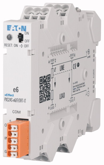
Reliable modular elektronic overcurrent protection for 24V DC systems, simple busbar solution, fixed or variable amperages, optionally with control input and tripped message output, plug-in terminals (+ 24V and 0V) for up to 3 loads, robust design, local and (optional) remote-controllable
| Basic function | Automation engineering 24V |
| Number of channels | 1 |
| Protection | Electronic |
| Rated current [In] | 10 A |
| Rated operating voltage [Un] | 24 V |
| Standard/Approval | in Arbeit |
| Operational voltage [UB] | 24 DC (16 .. 30V DC) |
| Rated operational current fix [IN] | 10 A |
| Overload current and short-circuit current trip | Type 1.3 x IN with active current limitation |
| Trip time for electronic trip | 90 ms |
| Capacitive loads | Up to 20,000 µF |
| Inductive loads | Up to 13 A |
| Width | 17.5 mm |
| Depth | 119.2 mm |
| Terminals >Input terminals |
3x LINE (+) and 3x GND (-) |
| Terminals >Output Terminals |
3x LOAD (+) and 3x GND (-) |
| Terminals >Terminal type: |
Push in terminals |
| Terminals >Terminal capacity |
2.5 (flexible with ferrules) 4 (rigid) mm² |
| Communication connector >Communication connector |
Two remote signaling outputs (internally connected to each other) Two remote signaling inputs (internally connected to each other) 1x GND |
| Communication connector >Terminal type: |
Push in terminals |
| Communication connector >Terminal capacity |
0.75 (flexible with ferrule) 1.5 (rigid) mm² |
| Communication connector >Remote signaling output |
Triggered Via communication connector (conforming to IEC 61131-2), class: 0.1 A Type1/Type2 and Type3 Digital inputs A max. of 30 PXS24V can be connected simultaneously External signal sources up to 0.2 A@24 V (EATON RMQ series, etc.) |
| Communication connector >Remote control input |
On/Off/Reset Via communication connector (conforming to IEC 61131-2), type 1/type 3 A max. of 30 PXS24V can be connected simultaneously |
| Communication connector >Sequential control |
Via communication connector |
| Busbars | LINE (+) and GND (-); max 60A in various lengths of up to 1m |
| Mounting | snap-fit on mounting rail TH35 (EN 60715) |
| Status LED | Two-colored Green = OK; Red = Triggered OFF = Channel not in operation |
| Slide switch | On/Off/Reset |
| Text field | 17,5 x 6 mm |
| Degree of Protection | IP20 |
| Ambient temperature | -30 - +55 °C |
| Permissible storage and transport temperatures | -40 - +100 °C |
| Base dimension | 92.5 mm |
| Rated operational current for specified heat dissipation [In] | 10 A |
| Equipment heat dissipation, current-dependent [Pvid] | 1.6 W |
| 10.2 Strength of materials and parts >10.2.2 Corrosion resistance |
Meets the product standard´s requirements. |
| 10.2 Strength of materials and parts >10.2.3.1 Verification of thermal stability of enclosures |
Meets the product standard´s requirements. |
| 10.2 Strength of materials and parts >10.2.3.2 Verification of resistance of insulating materials to normal heat |
Meets the product standard´s requirements. |
| 10.2 Strength of materials and parts >10.2.3.3 Verification of resistance of insulating materials to abnormal heat and fire due to internal electric effects |
Meets the product standard´s requirements. |
| 10.2 Strength of materials and parts >10.2.4 Resistance to ultra-violet (UV) radiation |
Meets the product standard´s requirements. |
| 10.2 Strength of materials and parts >10.2.5 Lifting |
Does not apply, since the entire switchgear needs to be evaluated. |
| 10.2 Strength of materials and parts >10.2.6 Mechanical impact |
Does not apply, since the entire switchgear needs to be evaluated. |
| 10.2 Strength of materials and parts >10.2.7 Inscriptions |
Meets the product standard´s requirements. |
| 10.3 Degree of protection of ASSEMBLIES | Does not apply, since the entire switchgear needs to be evaluated. |
| 10.4 Clearances and creepage distances | Meets the product standard´s requirements. |
| 10.5 Protection against electric shock | Does not apply, since the entire switchgear needs to be evaluated. |
| 10.6 Incorporation of switching devices and components | Does not apply, since the entire switchgear needs to be evaluated. |
| 10.7 Internal electrical circuits and connections | Is the panel builder´s responsibility. |
| 10.8 Connections for external conductors | Is the panel builder´s responsibility. |
| 10.9 Insulation properties >10.9.2 Power-frequency electric strength |
Is the panel builder´s responsibility. |
| 10.9 Insulation properties >10.9.3 Impulse withstand voltage |
Is the panel builder´s responsibility. |
| 10.9 Insulation properties >10.9.4 Testing of enclosures made of insulating material |
Is the panel builder´s responsibility. |
| 10.10 Temperature rise | The panel builder is responsible for the temperature rise calculation. Eaton will provide heat dissipation data for the devices. |
| 10.11 Short-circuit rating | Is the panel builder´s responsibility. The specifications for the switchgear must be observed. |
| 10.12 Electromagnetic compatibility | Is the panel builder´s responsibility. The specifications for the switchgear must be observed. |
| 10.13 Mechanical function | The device meets the requirements, provided the information in the instruction leaflet (IL) is observed. |
| Type of electric connection | Plug-in connection |
| With detachable clamps | No |
| Single-phase under current possible | No |
| Three-phase under current possible | No |
| Single-phase over current possible | No |
| Three-phase over current possible | No |
| Single-phase hysteresis possible | No |
| Three-phase hysteresis possible | No |
| Contains function DC-voltage under current | No |
| Contains function DC-voltage over current | Yes |
| Function DC-current hysteresis | No |
| Rated control supply voltage Us at AC 50HZ | 0 - 0 V |
| Rated control supply voltage Us at AC 60HZ | 0 - 0 V |
| Rated control supply voltage Us at DC | 16 - 30 V |
| Voltage type for actuating | DC |
| Current measurement range | 0 - 13 A |
| Min. adjustable delay-on energization time | 0 s |
| Max. permitted delay-on energization time | 0 s |
| Min. adjustable off-delay time | 0 s |
| Max. permitted off-delay time | 0 s |
| Number of contacts as normally closed contact | 0 |
| Number of contacts as normally open contact | 1 |
| Number of contacts as change-over contact | 0 |
| External current transformer | No |
| Width | 18 mm |
| Height | 93 mm |
| Depth | 127 mm |
Tüm hakları saklıdır. Mnelko Endüstriyel San. ve Tic.Ltd.Şti. 2024