SKU: Eaton-PXS24ACC0001
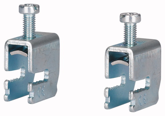
Feed-in terminals 2,5-16qmm for PXS24-BB
Accessories for the 24V PXS24 fuse; supply terminal directly to the bus bar, 2.5 -16mm2, max. 60A
| Basic function | Automation engineering 24V |
| Number of channels | 0 |
| Protection | none |
| Rated current [In] | 60 A |
| Rated operating voltage [Un] | 24 V |
| Operational voltage [UB] | 24 DC (16 .. 30V DC) |
| Mounting | can be snapped onto PXS24 modules |
| Ambient temperature | -30 - +55 °C |
| Permissible storage and transport temperatures | -40 - +100 °C |
| 10.2 Strength of materials and parts >10.2.2 Corrosion resistance |
Meets the product standard´s requirements. |
| 10.2 Strength of materials and parts >10.2.3.1 Verification of thermal stability of enclosures |
Meets the product standard´s requirements. |
| 10.2 Strength of materials and parts >10.2.3.2 Verification of resistance of insulating materials to normal heat |
Meets the product standard´s requirements. |
| 10.2 Strength of materials and parts >10.2.3.3 Verification of resistance of insulating materials to abnormal heat and fire due to internal electric effects |
Meets the product standard´s requirements. |
| 10.2 Strength of materials and parts >10.2.4 Resistance to ultra-violet (UV) radiation |
Meets the product standard´s requirements. |
| 10.2 Strength of materials and parts >10.2.5 Lifting |
Does not apply, since the entire switchgear needs to be evaluated. |
| 10.2 Strength of materials and parts >10.2.6 Mechanical impact |
Does not apply, since the entire switchgear needs to be evaluated. |
| 10.2 Strength of materials and parts >10.2.7 Inscriptions |
Meets the product standard´s requirements. |
| 10.3 Degree of protection of ASSEMBLIES | Does not apply, since the entire switchgear needs to be evaluated. |
| 10.4 Clearances and creepage distances | Meets the product standard´s requirements. |
| 10.5 Protection against electric shock | Does not apply, since the entire switchgear needs to be evaluated. |
| 10.6 Incorporation of switching devices and components | Does not apply, since the entire switchgear needs to be evaluated. |
| 10.7 Internal electrical circuits and connections | Is the panel builder´s responsibility. |
| 10.8 Connections for external conductors | Is the panel builder´s responsibility. |
| 10.9 Insulation properties >10.9.2 Power-frequency electric strength |
Is the panel builder´s responsibility. |
| 10.9 Insulation properties >10.9.3 Impulse withstand voltage |
Is the panel builder´s responsibility. |
| 10.9 Insulation properties >10.9.4 Testing of enclosures made of insulating material |
Is the panel builder´s responsibility. |
| 10.10 Temperature rise | The panel builder is responsible for the temperature rise calculation. Eaton will provide heat dissipation data for the devices. |
| 10.11 Short-circuit rating | Is the panel builder´s responsibility. The specifications for the switchgear must be observed. |
| 10.12 Electromagnetic compatibility | Is the panel builder´s responsibility. The specifications for the switchgear must be observed. |
| 10.13 Mechanical function | The device meets the requirements, provided the information in the instruction leaflet (IL) is observed. |
| Busbar thickness | 0 - 0 mm |
| Busbar width | 0 - 0 mm |
| Suitable for | T-rail |
| Width clamp | 7 mm |
| Max. conductor cross section | 16 mm² |
| Max. rated operation current Ie | 60 A |
| Suitable for round conductor connection | Yes |
| Suitable for sector conductor connection | No |
| Suitable for strip conductor connection | No |
Tüm hakları saklıdır. Mnelko Endüstriyel San. ve Tic.Ltd.Şti. 2024