SKU: Eaton-290377
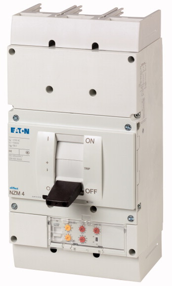
Circuit-breaker, 3p, 1000A 1000V
Circuit-breaker NZM4, 3 pole, Switching capacity 1000 V 50/60 Hz( Ics): 20 kA, Rated current = rated uninterrupted current( In = Iu): 1000 A, Installation type: Fixed, Screw connection, Standard/Approval: IEC, Protective function: Systems, cable, selectivity and generator protection
| Product range | Circuit-breaker |
| Protective function | Systems, cable, selectivity and generator protection |
| Standard/Approval | IEC |
| Installation type | Fixed |
| Release system | Electronic release |
| Construction size | NZM4 |
| Description | R.m.s. value measurement and “thermal memory” adjustable time delay setting to overcome current peaks tr: 2 – 20 s at 6 x Ir also infinity (without overload releases) Adjustable delay time tsd: Steps: 0, 20, 60, 100, 200, 300, 500, 750, 1000 ms i2t constant function: switchable NZM...S1 terminal type: NZM...XKSA cover required |
| Number of poles | 3 pole |
| Standard equipment | Screw connection |
| Rated current = rated uninterrupted current [In = Iu] | 1000 A |
| 1000 V 50/60 Hz [Icu] | 20 kA |
| Overload trip 500 - 1000 A
Short-circuit releases >Non-delayed |
500 - 1000 A |
| Short-circuit releases >Delayed |
2 - 12 |
| Rated surge voltage invariability [Uimp
] >Main contacts |
2 - 10 |
| Rated surge voltage invariability [Uimp
] >Auxiliary contacts |
8000 V |
| Rated operational voltage [Ue] | 6000 V |
| Rated current = rated uninterrupted current [In = Iu] | 1000 V AC |
| Overvoltage category/pollution degree | 1000 A |
| Rated insulation voltage [Ui ] | III/3 |
| Utilization category | 1000 V |
| Ambient temperature >Ambient temperature, storage |
B |
| Ambient temperature >Operation |
- 40 - + 70 °C |
| 240 V 50/60 Hz [Icm ] | -25 - +70 °C |
| 400/415 V 50/60 Hz [Icm ] | 275 kA |
| 440 V 50/60 Hz [Icm ] | 187 kA |
| 525 V 50/60 Hz [Icm ] | 187 kA |
| 690 V 50/60 H [Ic] | 143 kA |
| 1000 V 50/60 Hz [Icm] | 100 kA |
| Icu to IEC/EN 60947 test cycle O-t-CO [Icu] >240 V 50/60 Hz [Icu ] |
40 kA |
| Icu to IEC/EN 60947 test cycle O-t-CO [Icu] >400/415 V 50 Hz [Icu ] |
125 kA |
| Icu to IEC/EN 60947 test cycle O-t-CO [Icu] >440 V 50/60 Hz [Icu ] |
85 kA |
| Icu to IEC/EN 60947 test cycle O-t-CO [Icu] >525 V 50/60 Hz [Icu ] |
85 kA |
| Icu to IEC/EN 60947 test cycle O-t-CO [Icu] >690 V 50/60 Hz [Icu ] |
65 kA |
| Icu to IEC/EN 60947 test cycle O-t-CO [Icu] >1000 V 50/60 Hz [Icu] |
50 kA |
| Ics to IEC/EN 60947 test cycle O-t-CO-t-CO [Ics] >230 V 50/60 Hz [Ics ] |
20 kA |
| Ics to IEC/EN 60947 test cycle O-t-CO-t-CO [Ics] >400/415 V 50/60 Hz [Ics ] |
63 kA |
| Ics to IEC/EN 60947 test cycle O-t-CO-t-CO [Ics] >440 V 50/60 Hz [Ics ] |
50 kA |
| Ics to IEC/EN 60947 test cycle O-t-CO-t-CO [Ics] >525 V 50/60 Hz [Ics ] |
50 kA |
| Ics to IEC/EN 60947 test cycle O-t-CO-t-CO [Ics] >690 V 50/60 Hz [Ics] |
50 kA |
| Ics to IEC/EN 60947 test cycle O-t-CO-t-CO [Ics] >1000 V AC [Ics] |
37 kA |
| t = 0.3 s [Icw ] | 15 kA |
| t = 1 s [Icw ] | 19.2 kA |
| Lifespan, mechanical [Operations] | 19.2 kA |
| Max. operating frequency | 10000 |
| 1000 V 50/60 Hz [Operations] | 60 Ops/h |
| Standard equipment | Lifespan, mechanical: of which max. 50 % trip by shunt/undervoltage release |
| Round copper conductor >Tunnel terminal >Stranded >4-hole |
500 |
| Round copper conductor >Bolt terminal and rear-side connection >Module plate >Single hole [min.] |
Screw connection |
| Round copper conductor >Bolt terminal and rear-side connection >Module plate >Single hole [max.] |
4 x (50 - 240) mm2 |
| Round copper conductor >Bolt terminal and rear-side connection >Module plate >Double hole [min.] |
1 x (185 - 240) mm2 |
| Round copper conductor >Bolt terminal and rear-side connection >Module plate >Double hole [max.] |
2 x (70 - 185) mm2 |
| Round copper conductor >Bolt terminal and rear-side connection >Connection width extension >Connection width extension |
4 x 50 mm2 |
| Al conductors, Cu cable >Tunnel terminal >Stranded >4-hole |
4 x (35 - 185) mm2 |
| Cu strip (number of segments x width x segment thickness) >Flat conductor terminal [min.] |
2 x 240 6 x (70 - 240) mm2 |
| Cu strip (number of segments x width x segment thickness) >Flat conductor terminal [max.] |
4 x (50 - 240) mm2 |
| Cu strip (number of segments x width x segment thickness) >Module plate >Single hole |
6 x 16 x 0.8 mm |
| Cu strip (number of segments x width x segment thickness) >Bolt terminal and rear-side connection >Flat copper strip, with holes [min.] |
(2 x) 10 x 32 x 1.0 mm |
| Cu strip (number of segments x width x segment thickness) >Bolt terminal and rear-side connection >Flat copper strip, with holes [max.] |
(2 x) 10 x 50 x 1.0 mm |
| Cu strip (number of segments x width x segment thickness) >Bolt terminal and rear-side connection >Connection width extension |
(2 x) 10 x 50 x 1.0 mm |
| Copper busbar (width x thickness) [mm] >Bolt terminal and rear-side connection >Screw connection |
(2 x) 10 x 50 x 1.0 mm |
| Copper busbar (width x thickness) [mm] >Bolt terminal and rear-side connection >Direct on the switch [min.] |
(2 x) 10 x 80 x 1.0 mm |
| Copper busbar (width x thickness) [mm] >Bolt terminal and rear-side connection >Direct on the switch [max.] |
M10 |
| Copper busbar (width x thickness) [mm] >Bolt terminal and rear-side connection >Module plate >Single hole [min.] |
25 x 5 mm |
| Copper busbar (width x thickness) [mm] >Bolt terminal and rear-side connection >Module plate >Single hole [max.] |
2 x (50 x 10) 2 x (80 x 10) mm |
| Copper busbar (width x thickness) [mm] >Bolt terminal and rear-side connection >Module plate >Double hole |
25 x 5 mm |
| Copper busbar (width x thickness) [mm] >Bolt terminal and rear-side connection >Connection width extension >Connection width extension [min.] |
2 x (50 x 10) mm |
| Copper busbar (width x thickness) [mm] >Bolt terminal and rear-side connection >Connection width extension >Connection width extension [max.] |
2 x (50 x 10) mm |
| Control cables | 60 x 10 mm |
| Rated operational current for specified heat dissipation [In] | 2 x (80 x 10) mm |
| Equipment heat dissipation, current-dependent [Pvid] | 1 x (0.75 - 2.5) 2 x (0.75 - 1.5) mm2 |
| Operating ambient temperature min. | 1000 A |
| Operating ambient temperature max. | 123 W |
| 10.2 Strength of materials and parts >10.2.2 Corrosion resistance |
-25 °C |
| 10.2 Strength of materials and parts >10.2.3.1 Verification of thermal stability of enclosures |
+70 °C |
| 10.2 Strength of materials and parts >10.2.3.2 Verification of resistance of insulating materials to normal heat |
Meets the product standard´s requirements. |
| 10.2 Strength of materials and parts >10.2.3.3 Verification of resistance of insulating materials to abnormal heat and fire due to internal electric effects |
Meets the product standard´s requirements. |
| 10.2 Strength of materials and parts >10.2.4 Resistance to ultra-violet (UV) radiation |
Meets the product standard´s requirements. |
| 10.2 Strength of materials and parts >10.2.5 Lifting |
Meets the product standard´s requirements. |
| 10.2 Strength of materials and parts >10.2.6 Mechanical impact |
Meets the product standard´s requirements. |
| 10.2 Strength of materials and parts >10.2.7 Inscriptions |
Does not apply, since the entire switchgear needs to be evaluated. |
| 10.3 Degree of protection of ASSEMBLIES | Does not apply, since the entire switchgear needs to be evaluated. |
| 10.4 Clearances and creepage distances | Meets the product standard´s requirements. |
| 10.5 Protection against electric shock | Does not apply, since the entire switchgear needs to be evaluated. |
| 10.6 Incorporation of switching devices and components | Meets the product standard´s requirements. |
| 10.7 Internal electrical circuits and connections | Does not apply, since the entire switchgear needs to be evaluated. |
| 10.8 Connections for external conductors | Does not apply, since the entire switchgear needs to be evaluated. |
| 10.9 Insulation properties >10.9.2 Power-frequency electric strength |
Is the panel builder´s responsibility. |
| 10.9 Insulation properties >10.9.3 Impulse withstand voltage |
Is the panel builder´s responsibility. |
| 10.9 Insulation properties >10.9.4 Testing of enclosures made of insulating material |
Is the panel builder´s responsibility. |
| 10.10 Temperature rise | Is the panel builder´s responsibility. |
| 10.11 Short-circuit rating | Is the panel builder´s responsibility. |
| 10.12 Electromagnetic compatibility | The panel builder is responsible for the temperature rise calculation. Eaton will provide heat dissipation data for the devices. |
| 10.13 Mechanical function | Is the panel builder´s responsibility. The specifications for the switchgear must be observed. |
| Rated permanent current Iu | Is the panel builder´s responsibility. The specifications for the switchgear must be observed. |
| Rated voltage | The device meets the requirements, provided the information in the instruction leaflet (IL) is observed. |
| Rated short-circuit breaking capacity lcu at 400 V, 50 Hz | 1000 A |
| Overload release current setting | 1000 - 1000 V |
| Adjustment range short-term delayed short-circuit release | 85 kA |
| Adjustment range undelayed short-circuit release | 500 - 1000 A |
| Integrated earth fault protection | 1000 - 1000 A |
| Type of electrical connection of main circuit | 2000 - 12000 A |
| Device construction | No |
| Suitable for DIN rail (top hat rail) mounting | Screw connection |
| DIN rail (top hat rail) mounting optional | Built-in device fixed built-in technique |
| Number of auxiliary contacts as normally closed contact | No |
| Number of auxiliary contacts as normally open contact | No |
| Number of auxiliary contacts as change-over contact | 0 |
| With switched-off indicator | 0 |
| With under voltage release | 0 |
| Number of poles | No |
| Position of connection for main current circuit | No |
| Type of control element | 3 |
| Complete device with protection unit | Front side |
| Motor drive integrated | Rocker lever |
| Motor drive optional | Yes |
| Degree of protection (IP) | No |
| Characteristic curve | Yes |
| Characteristic curve | IP20 |
Tüm hakları saklıdır. Mnelko Endüstriyel San. ve Tic.Ltd.Şti. 2024