SKU: Eaton-285556
Earth-leakage circuit-breakers 300 mA
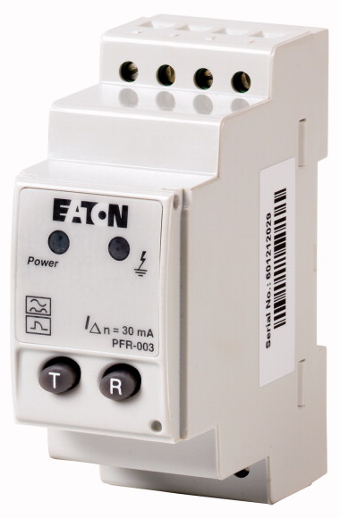
Optional accessories for the circuit-breaker series NZM offers a comprehensive portfolio of application options for use world wide. The mounting is always flexible and easy thanks to the modular function groups. Notes: pulsed current sensitive. Rated control voltage: Us = 230VAC (50/60 Hz). Integrated auxiliary contact (1 C/O). Ring-type transformer must also be ordered. Not UL/CSA approved. Can be used for: NZM1, NZM1-4, N1, N1-4, NZM2, NZM2-4, N2, N2-4, NZM3, NZM3-4, N3, N3-4, NZM4, NZM4-4, N4-4
| Rated fault currents [ I Δn ] | 0.3 A |
| Description | Pulse-current sensitive Integrated auxiliary contact (1 C/O) Ring-type transformer must also be ordered not UL/CSA approved |
| Rated control voltage [Us ] | 230 V AC 50/60Hz V |
| Standards | IEC/EN 60947-2, IEC 755, IEC 1008, IEC 1009 |
| Sensitivity | Pulse current sensitive, type A |
| Rated control voltage [Us] | 230 ±20 % (50/60 Hz) V AC |
| Motor rating [Pe] | 3 W |
| Rated fault currents [ I Δn ] | 0.3 A |
| Delay time [tv] | 0.02 (non-delayed) s |
| Relay contacts | 1 integrated changeover contact |
| Rated voltage of the relay contact | 250/100 V AC/DC |
| Rated current of the relay contact | 6 A |
| Standard front dimension | 45 mm |
| Enclosure height | 85 mm |
| Device width | 45 mm |
| Mounting | Snap fixing, top-hat rail DIN 46277, IEC/EN 60715 |
| Terminals top and bottom | Box terminals |
| Terminal protection | Finger/back-of-hand proof to BGV A2, VDE 106 part 100 |
| Terminal capacities | 2 x 0.75 - 2.5 solid, 2 x 0.75 - 1.5 flexible/with ferrules mm2 |
| Operation | -10 - +50 °C |
| Operating ambient temperature min. | -10 °C |
| Operating ambient temperature max. | +50 °C |
| 10.2 Strength of materials and parts >10.2.2 Corrosion resistance |
Meets the product standard´s requirements. |
| 10.2 Strength of materials and parts >10.2.3.1 Verification of thermal stability of enclosures |
Meets the product standard´s requirements. |
| 10.2 Strength of materials and parts >10.2.3.2 Verification of resistance of insulating materials to normal heat |
Meets the product standard´s requirements. |
| 10.2 Strength of materials and parts >10.2.3.3 Verification of resistance of insulating materials to abnormal heat and fire due to internal electric effects |
Meets the product standard´s requirements. |
| 10.2 Strength of materials and parts >10.2.4 Resistance to ultra-violet (UV) radiation |
Meets the product standard´s requirements. |
| 10.2 Strength of materials and parts >10.2.5 Lifting |
Does not apply, since the entire switchgear needs to be evaluated. |
| 10.2 Strength of materials and parts >10.2.6 Mechanical impact |
Does not apply, since the entire switchgear needs to be evaluated. |
| 10.2 Strength of materials and parts >10.2.7 Inscriptions |
Meets the product standard´s requirements. |
| 10.3 Degree of protection of ASSEMBLIES | Does not apply, since the entire switchgear needs to be evaluated. |
| 10.4 Clearances and creepage distances | Meets the product standard´s requirements. |
| 10.5 Protection against electric shock | Does not apply, since the entire switchgear needs to be evaluated. |
| 10.6 Incorporation of switching devices and components | Does not apply, since the entire switchgear needs to be evaluated. |
| 10.7 Internal electrical circuits and connections | Is the panel builder´s responsibility. |
| 10.8 Connections for external conductors | Is the panel builder´s responsibility. |
| 10.9 Insulation properties >10.9.2 Power-frequency electric strength |
Is the panel builder´s responsibility. |
| 10.9 Insulation properties >10.9.3 Impulse withstand voltage |
Is the panel builder´s responsibility. |
| 10.9 Insulation properties >10.9.4 Testing of enclosures made of insulating material |
Is the panel builder´s responsibility. |
| 10.10 Temperature rise | The panel builder is responsible for the temperature rise calculation. Eaton will provide heat dissipation data for the devices. |
| 10.11 Short-circuit rating | Is the panel builder´s responsibility. The specifications for the switchgear must be observed. |
| 10.12 Electromagnetic compatibility | Is the panel builder´s responsibility. The specifications for the switchgear must be observed. |
| 10.13 Mechanical function | The device meets the requirements, provided the information in the instruction leaflet (IL) is observed. |
| Rated control supply voltage Us at AC 50HZ | 184 - 276 V |
| Rated control supply voltage Us at AC 60HZ | 184 - 276 V |
| Rated control supply voltage Us at DC | 0 - 0 V |
| Rated fault current | 0.3 - 0.3 A |
| Max. power on-delay time | 20 ms |
| Delay adjustable | No |
| Max. rated operation voltage Ue | 276 V |
Tüm hakları saklıdır. Mnelko Endüstriyel San. ve Tic.Ltd.Şti. 2024