SKU: Eaton-283218
Circuit-breakers 3p 550 A
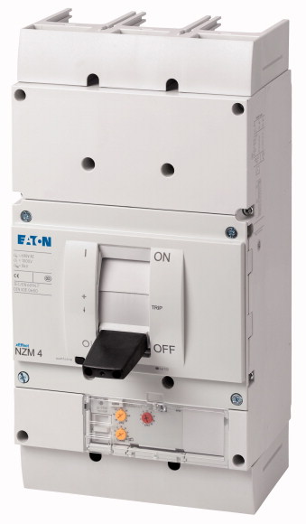
Circuit-breakers of the NZM..-ME series cover all applications with only four compact sizes and are suitable for the IEC market. The mounting is always flexible due to the modular function groups. With electronic release for the motor protection with phase failure sensitivity. Notes: IEC/EN 60947-4-1, IEC/EN 60947-2, r.m.s. value measurement and thermal memory, adjustable time delay setting to overcome current peaks tr:2-20 at 6xIr as well as infinity (without overload release)
| Product range | Circuit-breaker | ||||||||||||
| Protective function | Motor protection | ||||||||||||
| Standard/Approval | |||||||||||||
| Installation type | IEC | ||||||||||||
| Release system | Fixed | ||||||||||||
| Construction size | Electronic release | ||||||||||||
| Description | NZM4 | ||||||||||||
| Number of poles | IEC/EN 60947-4-1, IEC/EN 60947-2 The circuit-breaker fulfills all requirements for AC-3 switching category. R.m.s. value measurement and “thermal memory” Adjustable time delay setting to overcome current peaks tr at 6 x Ir also infinity (without overload releases) All AC-3 rating data applies to direct switching by the circuit-breaker under normal operating conditions. If, for example, a contactor takes over AC-3 switching under normal operating conditions, the full rated uninterrupted current applies to the circuit-breaker, In = Iu. |
||||||||||||
| Standard equipment | 3 pole | ||||||||||||
| 400/415 V 50 Hz [Icu ] | Screw connection | ||||||||||||
| Rated current = rated uninterrupted current [In = Iu] | 100 kA | ||||||||||||
| Overload trip 275 - 550 A
Short-circuit releases >Non-delayed |
550 A | ||||||||||||
| 380 V 400 V [P] | 275 - 550 A | ||||||||||||
| 660 V 690 V [P] | 2 - 14 | ||||||||||||
| 400 V [P] | 315 kW | ||||||||||||
| 660 V 690 V [P] | 560 kW | ||||||||||||
| 400 V [Ie ] | 315 kW | ||||||||||||
| 690 V | 560 kW | ||||||||||||
| Standards | 544 A | ||||||||||||
| Protection against direct contact | 550 A | ||||||||||||
| Climatic proofing | IEC/EN 60947 | ||||||||||||
| Ambient temperature >Ambient temperature, storage |
Finger and back of hand proof to VDE 0106 Part 100 | ||||||||||||
| Ambient temperature >Operation |
Damp heat, constant, to IEC 60068-2-78 Damp heat, cyclic, to IEC 60068-2-30 |
||||||||||||
| Mechanical shock resistance (10 ms half-sinusoidal shock) according to IEC 60068-2-27 | - 40 - + 70 °C | ||||||||||||
| Safe isolation to EN 61140 >Between auxiliary contacts and main contacts |
-25 - +70 °C | ||||||||||||
| Safe isolation to EN 61140 >between the auxiliary contacts |
15 (half-sinusoidal shock 11 ms) g | ||||||||||||
| Weight | 500 V AC | ||||||||||||
| Mounting position | 300 V AC | ||||||||||||
| Direction of incoming supply | 0 kg | ||||||||||||
| Degree of protection >Device |
|
||||||||||||
| Degree of protection >Enclosures |
as required | ||||||||||||
| Degree of protection >Terminations |
In the operating controls area: IP20 (basic degree of protection) | ||||||||||||
| Other technical data (sheet catalogue) | With insulating surround: IP40 With door coupling rotary handle: IP66 |
||||||||||||
| Rated current = rated uninterrupted current [In = Iu] | Tunnel terminal: IP10 Phase isolator and strip terminal: IP00 |
||||||||||||
| Rated surge voltage invariability [Uimp
] >Main contacts |
Temperature dependency, Derating | ||||||||||||
| Rated surge voltage invariability [Uimp
] >Auxiliary contacts |
550 A | ||||||||||||
| Rated operational voltage [Ue] | 8000 V | ||||||||||||
| Overvoltage category/pollution degree | 6000 V | ||||||||||||
| Rated insulation voltage [Ui ] | 690 V AC | ||||||||||||
| Use in unearthed supply systems | III/3 | ||||||||||||
| Rated short-circuit making capacity [Icm
] >240 V [Icm ] |
1000 V | ||||||||||||
| Rated short-circuit making capacity [Icm
] >400/415 V [Icm ] |
≦ 690 V | ||||||||||||
| Rated short-circuit making capacity [Icm
] >440 V 50/60 Hz [Icm ] |
275 kA | ||||||||||||
| Rated short-circuit making capacity [Icm
] >525 V 50/60 Hz [Icm ] |
220 kA | ||||||||||||
| Rated short-circuit making capacity [Icm
] >690 V 50/60 H [Ic] |
187 kA | ||||||||||||
| Rated short-circuit breaking capacity Icn [Icn
] >Icu to IEC/EN 60947 test cycle O-t-CO [Icu] >240 V 50/60 Hz [Icu ] |
143 kA | ||||||||||||
| Rated short-circuit breaking capacity Icn [Icn
] >Icu to IEC/EN 60947 test cycle O-t-CO [Icu] >400/415 V 50/60 Hz [Icu ] |
105 kA | ||||||||||||
| Rated short-circuit breaking capacity Icn [Icn
] >Icu to IEC/EN 60947 test cycle O-t-CO [Icu] >440 V 50/60 Hz [Icu ] |
125 kA | ||||||||||||
| Rated short-circuit breaking capacity Icn [Icn
] >Icu to IEC/EN 60947 test cycle O-t-CO [Icu] >525 V 50/60 Hz [Icu ] |
100 kA | ||||||||||||
| Rated short-circuit breaking capacity Icn [Icn
] >Icu to IEC/EN 60947 test cycle O-t-CO [Icu] >690 V 50/60 Hz [Icu ] |
85 kA | ||||||||||||
| Rated short-circuit breaking capacity Icn [Icn
] >Ics to IEC/EN 60947 test cycle O-t-CO-t-CO [Ics] >240 V 50/60 Hz [Ics ] |
65 kA | ||||||||||||
| Rated short-circuit breaking capacity Icn [Icn
] >Ics to IEC/EN 60947 test cycle O-t-CO-t-CO [Ics] >400/415 V 50/60 Hz [Ics ] |
50 kA | ||||||||||||
| Rated short-circuit breaking capacity Icn [Icn
] >Ics to IEC/EN 60947 test cycle O-t-CO-t-CO [Ics] >440 V 50/60 Hz [Ics ] |
63 kA | ||||||||||||
| Rated short-circuit breaking capacity Icn [Icn
] >Ics to IEC/EN 60947 test cycle O-t-CO-t-CO [Ics] >525 V 50/60 Hz [Ics ] |
50 kA | ||||||||||||
| Rated short-circuit breaking capacity Icn [Icn
] >Ics to IEC/EN 60947 test cycle O-t-CO-t-CO [Ics] >690 V 50/60 Hz [Ics] |
43 kA | ||||||||||||
| Rated short-circuit breaking capacity Icn [Icn ] | 49 kA | ||||||||||||
| Rated short-time withstand current >t = 0.3 s [Icw ] |
37 kA | ||||||||||||
| Rated short-time withstand current >t = 1 s [Icw ] |
Maximum back-up fuse, if the expected short-circuit currents at the installation location exceed the switching capacity of the circuit-breaker. | ||||||||||||
| Utilization category to IEC/EN 60947-2 | 19.2 kA | ||||||||||||
| Lifespan, mechanical(of which max. 50 % trip by shunt/undervoltage release) [Operations] | 19.2 kA | ||||||||||||
| Lifespan, electrical >AC-1 >400 V 50/60 Hz [Operations] |
B | ||||||||||||
| Lifespan, electrical >AC-1 >415 V 50/60 Hz [Operations] |
10000 | ||||||||||||
| Lifespan, electrical >AC-1 >690 V 50/60 Hz [Operations] |
3000 | ||||||||||||
| Lifespan, electrical >AC--3 >400 V 50/60 Hz [Operations] |
3000 | ||||||||||||
| Lifespan, electrical >AC--3 >415 V 50/60 Hz [Operations] |
2000 | ||||||||||||
| Lifespan, electrical >AC--3 >690 V 50/60 Hz [Operations] |
2000 | ||||||||||||
| Lifespan, electrical >Max. operating frequency |
2000 | ||||||||||||
| Total break time at short-circuit | 1000 | ||||||||||||
| Standard equipment | 60 Ops/h | ||||||||||||
| Optional accessories | < 25 ≦ 415 V; < 35 > 415 V ms | ||||||||||||
| Round copper conductor >Tunnel terminal >Stranded >4-hole |
Screw connection | ||||||||||||
| Round copper conductor >Bolt terminal and rear-side connection >Direct on the switch >Stranded |
Tunnel terminal connection on rear Strip terminal |
||||||||||||
| Round copper conductor >Bolt terminal and rear-side connection >Module plate >Single hole [min.] |
4 x (50 - 240) mm2 | ||||||||||||
| Round copper conductor >Bolt terminal and rear-side connection >Module plate >Single hole [max.] |
1 x (120 - 185) 4 x (50 - 185) mm2 |
||||||||||||
| Round copper conductor >Bolt terminal and rear-side connection >Module plate >Double hole [min.] |
1 x (120 - 300) mm2 | ||||||||||||
| Round copper conductor >Bolt terminal and rear-side connection >Module plate >Double hole [max.] |
2 x (95 - 300) mm2 | ||||||||||||
| Round copper conductor >Bolt terminal and rear-side connection >Connection width extension >Connection width extension |
2 x (95 - 185) mm2 | ||||||||||||
| Al circular conductor >Tunnel terminal >Stranded >4-hole |
4 x (35 - 185) mm2 | ||||||||||||
| Cu strip (number of segments x width x segment thickness) >Flat conductor terminal [min.] |
4 x 300 6 x (95 - 240) mm2 |
||||||||||||
| Cu strip (number of segments x width x segment thickness) >Flat conductor terminal [max.] |
4 x (50 - 240) mm2 | ||||||||||||
| Cu strip (number of segments x width x segment thickness) >Module plate >Single hole |
6 x 16 x 0.8 mm | ||||||||||||
| Cu strip (number of segments x width x segment thickness) >Bolt terminal and rear-side connection >Flat copper strip, with holes [min.] |
(2 x) 10 x 32 x 1.0 mm | ||||||||||||
| Cu strip (number of segments x width x segment thickness) >Bolt terminal and rear-side connection >Flat copper strip, with holes [max.] |
(2 x) 10 x 50 x 1.0 mm | ||||||||||||
| Cu strip (number of segments x width x segment thickness) >Bolt terminal and rear-side connection >Connection width extension |
5 x 25 x 1.0 mm | ||||||||||||
| Copper busbar (width x thickness) [mm] >Bolt terminal and rear-side connection >Screw connection |
(2 x) 10 x 50 x 1.0 mm | ||||||||||||
| Copper busbar (width x thickness) [mm] >Bolt terminal and rear-side connection >Direct on the switch [min.] |
(2 x) 10 x 80 x 1.0 mm | ||||||||||||
| Copper busbar (width x thickness) [mm] >Bolt terminal and rear-side connection >Direct on the switch [max.] |
M10 | ||||||||||||
| Copper busbar (width x thickness) [mm] >Bolt terminal and rear-side connection >Module plate >Single hole [min.] |
25 x 5 mm | ||||||||||||
| Copper busbar (width x thickness) [mm] >Bolt terminal and rear-side connection >Module plate >Single hole [max.] |
2 x (50 x 10) mm | ||||||||||||
| Copper busbar (width x thickness) [mm] >Bolt terminal and rear-side connection >Module plate >Double hole |
25 x 5 mm | ||||||||||||
| Copper busbar (width x thickness) [mm] >Bolt terminal and rear-side connection >Connection width extension >Connection width extension [min.] |
2 x (50 x 10) mm | ||||||||||||
| Copper busbar (width x thickness) [mm] >Bolt terminal and rear-side connection >Connection width extension >Connection width extension [max.] |
2 x (50 x 10) mm | ||||||||||||
| Control cables | 60 x 10 mm | ||||||||||||
| Rated operational current for specified heat dissipation [In] | 2 x (80 x 10) mm | ||||||||||||
| Equipment heat dissipation, current-dependent [Pvid] | 1 x (0.75 - 2.5) 2 x (0.75 - 1.5) mm2 |
||||||||||||
| Operating ambient temperature min. | 550 A | ||||||||||||
| Operating ambient temperature max. | 33.58 W | ||||||||||||
| 10.2 Strength of materials and parts >10.2.2 Corrosion resistance |
-25 °C | ||||||||||||
| 10.2 Strength of materials and parts >10.2.3.1 Verification of thermal stability of enclosures |
+70 °C | ||||||||||||
| 10.2 Strength of materials and parts >10.2.3.2 Verification of resistance of insulating materials to normal heat |
Meets the product standard´s requirements. | ||||||||||||
| 10.2 Strength of materials and parts >10.2.3.3 Verification of resistance of insulating materials to abnormal heat and fire due to internal electric effects |
Meets the product standard´s requirements. | ||||||||||||
| 10.2 Strength of materials and parts >10.2.4 Resistance to ultra-violet (UV) radiation |
Meets the product standard´s requirements. | ||||||||||||
| 10.2 Strength of materials and parts >10.2.5 Lifting |
Meets the product standard´s requirements. | ||||||||||||
| 10.2 Strength of materials and parts >10.2.6 Mechanical impact |
Meets the product standard´s requirements. | ||||||||||||
| 10.2 Strength of materials and parts >10.2.7 Inscriptions |
Does not apply, since the entire switchgear needs to be evaluated. | ||||||||||||
| 10.3 Degree of protection of ASSEMBLIES | Does not apply, since the entire switchgear needs to be evaluated. | ||||||||||||
| 10.4 Clearances and creepage distances | Meets the product standard´s requirements. | ||||||||||||
| 10.5 Protection against electric shock | Does not apply, since the entire switchgear needs to be evaluated. | ||||||||||||
| 10.6 Incorporation of switching devices and components | Meets the product standard´s requirements. | ||||||||||||
| 10.7 Internal electrical circuits and connections | Does not apply, since the entire switchgear needs to be evaluated. | ||||||||||||
| 10.8 Connections for external conductors | Does not apply, since the entire switchgear needs to be evaluated. | ||||||||||||
| 10.9 Insulation properties >10.9.2 Power-frequency electric strength |
Is the panel builder´s responsibility. | ||||||||||||
| 10.9 Insulation properties >10.9.3 Impulse withstand voltage |
Is the panel builder´s responsibility. | ||||||||||||
| 10.9 Insulation properties >10.9.4 Testing of enclosures made of insulating material |
Is the panel builder´s responsibility. | ||||||||||||
| 10.10 Temperature rise | Is the panel builder´s responsibility. | ||||||||||||
| 10.11 Short-circuit rating | Is the panel builder´s responsibility. | ||||||||||||
| 10.12 Electromagnetic compatibility | The panel builder is responsible for the temperature rise calculation. Eaton will provide heat dissipation data for the devices. | ||||||||||||
| 10.13 Mechanical function | Is the panel builder´s responsibility. The specifications for the switchgear must be observed. | ||||||||||||
| Overload release current setting | Is the panel builder´s responsibility. The specifications for the switchgear must be observed. | ||||||||||||
| Adjustment range undelayed short-circuit release | The device meets the requirements, provided the information in the instruction leaflet (IL) is observed. | ||||||||||||
| With thermal protection | 275 - 550 A | ||||||||||||
| Phase failure sensitive | 550 - 7700 A | ||||||||||||
| Switch off technique | Yes | ||||||||||||
| Rated operating voltage | Yes | ||||||||||||
| Rated permanent current Iu | Electronic | ||||||||||||
| Rated operation power at AC-3, 230 V | 690 - 690 V | ||||||||||||
| Rated operation power at AC-3, 400 V | 550 A | ||||||||||||
| Type of electrical connection of main circuit | 160 kW | ||||||||||||
| Type of control element | 315 kW | ||||||||||||
| Device construction | Screw connection | ||||||||||||
| With integrated auxiliary switch | Rocker lever | ||||||||||||
| With integrated under voltage release | Built-in device fixed built-in technique | ||||||||||||
| Number of poles | No | ||||||||||||
| Rated short-circuit breaking capacity lcu at 400 V, AC | No | ||||||||||||
| Degree of protection (IP) | 4 | ||||||||||||
| Height | 100 kA | ||||||||||||
| Width | IP20 | ||||||||||||
| Depth | 207 mm | ||||||||||||
| Characteristic curve | 210 mm | ||||||||||||
Tüm hakları saklıdır. Mnelko Endüstriyel San. ve Tic.Ltd.Şti. 2024