SKU: Eaton-266754
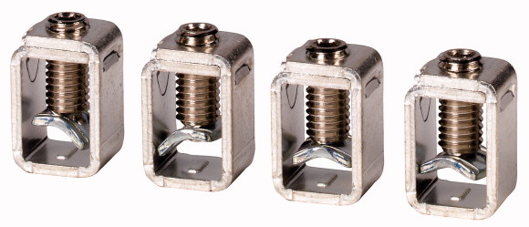
Box terminal, 4p, bottom up to 300A
Optional accessories for circuit-breaker series NZM offers a comprehensive portfolio of application possibilities for worldwide use. Modular functional groups make mounting flexible and simple. Notes: part no. suffix and part no. contain parts for a circuit-breaker side at top or bottom for 3 or 4 pole circuit-breakers. Conversion kit for circuit-breaker with screw connection. Fitted within the switch housing. O = for fitting at the top. U = for fitting at the bottom. U e ≧ 525 VAC. Use cover NZM2(-4)-XKSA. Use ferrules with flexible and highly flexible conductors. Max. cross section shown can only be connected when flexible and without ferrules. Can be used for: NZM2(-4), PN2(-4), N(N/O)2(-4)
| Number of conductors | 4 pole |
| Accessories | Box terminal |
| Rated current [In] | ≦ 300 A |
| For use with | NZM2(-4), PN2(-4), N(S)2(-4) |
| Mounting position | Fitted at the bottom |
| Type of conductor >Cu/Al cable |
|
| Terminal capacities >flexible |
Cu cable |
| AWG/kcmil | 1 x 10 - 185 2 x 4 - 70 Up to 95 mm² can be connected depending on the cable manufacturer. mm2 |
| Cu strip (number of segments x width x segment thickness) | 1 x 12 - 350 mm2 |
| Notes | |
| Mounting position | min. 2 x 9 x 0.8 max. 10 x 16 x 0.8 Or max. (2 x) 8 x 15.5 x 0.8 mm2 |
| 10.2 Strength of materials and parts >10.2.2 Corrosion resistance |
Type suffix and type contain parts for a circuit-breaker side at top or bottom for 3 or 4 pole circuit-breakers. Conversion kit for circuit-breaker with screw connection. Fitted within the switch housing O = for fitting at the top U = for fitting at the bottom Ue ≧ 525 V AC:
Use ferrules with flexible and highly flexible conductors. Max. cross section shown can only be connected when flexible and without ferrules. |
| 10.2 Strength of materials and parts >10.2.3.1 Verification of thermal stability of enclosures |
|
| 10.2 Strength of materials and parts >10.2.3.2 Verification of resistance of insulating materials to normal heat |
Fitted at the bottom |
| 10.2 Strength of materials and parts >10.2.3.3 Verification of resistance of insulating materials to abnormal heat and fire due to internal electric effects |
|
| 10.2 Strength of materials and parts >10.2.4 Resistance to ultra-violet (UV) radiation |
Meets the product standard´s requirements. |
| 10.2 Strength of materials and parts >10.2.5 Lifting |
Meets the product standard´s requirements. |
| 10.2 Strength of materials and parts >10.2.6 Mechanical impact |
Meets the product standard´s requirements. |
| 10.2 Strength of materials and parts >10.2.7 Inscriptions |
Meets the product standard´s requirements. |
| 10.3 Degree of protection of ASSEMBLIES | Meets the product standard´s requirements. |
| 10.4 Clearances and creepage distances | Does not apply, since the entire switchgear needs to be evaluated. |
| 10.5 Protection against electric shock | Does not apply, since the entire switchgear needs to be evaluated. |
| 10.6 Incorporation of switching devices and components | Meets the product standard´s requirements. |
| 10.7 Internal electrical circuits and connections | Does not apply, since the entire switchgear needs to be evaluated. |
| 10.8 Connections for external conductors | Meets the product standard´s requirements. |
| 10.9 Insulation properties >10.9.2 Power-frequency electric strength |
Does not apply, since the entire switchgear needs to be evaluated. |
| 10.9 Insulation properties >10.9.3 Impulse withstand voltage |
Does not apply, since the entire switchgear needs to be evaluated. |
| 10.9 Insulation properties >10.9.4 Testing of enclosures made of insulating material |
Is the panel builder´s responsibility. |
| 10.10 Temperature rise | Is the panel builder´s responsibility. |
| 10.11 Short-circuit rating | Is the panel builder´s responsibility. |
| 10.12 Electromagnetic compatibility | Is the panel builder´s responsibility. |
| 10.13 Mechanical function | Is the panel builder´s responsibility. |
| Suitable for number of poles | The panel builder is responsible for the temperature rise calculation. Eaton will provide heat dissipation data for the devices. |
| Model | Is the panel builder´s responsibility. The specifications for the switchgear must be observed. |
Tüm hakları saklıdır. Mnelko Endüstriyel San. ve Tic.Ltd.Şti. 2024