SKU: Eaton-183056
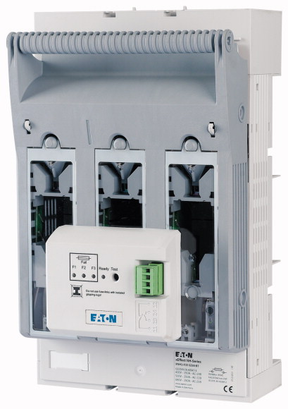
NH fuse-switch 3p box terminal 35 - 150 mm²; busbar 60 mm; electronic fuse monitoring; NH1
NH fuse switch-disconnector 3 pole with box terminal 35 - 150 mm²; busbar 60 mm; electronic fuse monitoring; for NH1 fuse-links; smartWire ready with XNH...-SWD-KIT; upper/lower cable connection can be changed in seconds.
| Basic function | Fuse control - electronic |
| Number of poles | 3 pole |
| Mounting type | Busbars of 60 mm |
| Size | 1 |
| Type of connection | Box terminal |
| Rated operational current [Ie] | 250 A |
| Front degree of protection (XNH installed) | IP20 (Operating status) IP2XC (Contact protection) IP10 (Handle cover open) |
| Rated operational voltage [Ue ] | 690 V AC |
| Rated operational voltage [Ue] | 440 V DC |
| Rated conditional short-circuit current | 120 (500 V) 100 (690 V) kA |
| Flammability characteristics | Self-extinguishing as per UL 94 |
| Description | Current paths of electrolytic copper, silver-plated Cable connection optionally at the top or bottom With electronic monitoring of fuse-links |
| Standards | IEC/EN 60947-3 |
| Rated operational voltage [Ue ] | 690 V AC |
| Rated operational voltage [Ue] | 440 V DC |
| Rated operational current [Ie] | 250 A |
| Rated frequency [f] | 40 - 60 Hz |
| Rated insulation voltage [Ui] | 800 V AC |
| Total heat dissipation at Ith (without fuses) [Pv] | 22 W |
| Heat dissipation at 80% (without fuses) [Pv] | 14.1 W |
| Rated impulse withstand voltage [Uimp] | 8 kV |
| Utilization category AC-23B >Rated operating voltage [Ue] |
400 V AC |
| Utilization category AC-23B >Rated operating current [Ie] |
250 A |
| Utilization category AC22B >Rated operating voltage [Ue] |
500 V AC |
| Utilization category AC22B >Rated operating current [Ie] |
250 A |
| Utilization category AC-21B >Rated operating voltage [Ue] |
690 V AC |
| Utilization category AC-21B >Rated operating current [Ie] |
250 A |
| Utilization category
DC-22B >Rated operating voltage [Ue] |
DC values on request V DC |
| Utilization category
DC-22B >Rated operating current [Ie] |
DC values on request A |
| Utilization category DC21B >Rated operating voltage [Ue] |
DC values on request V DC |
| Utilization category DC21B >Rated operating current [Ie] |
DC values on request A |
| Rated conditional short-circuit current | 120 (500 V) 100 (690 V) kA |
| Rated short-time withstand current [Icw] | 10 kA |
| Max. fuse >Size according to DIN VDE 0636-2 |
1 |
| Max. fuse >Max. permitted power loss per fuse link [Pv] |
23 W |
| Lifespan, electrical [Operations] | 200 |
| Front degree of protection (XNH installed) | IP20 (Operating status) IP2XC (Contact protection) IP10 (Handle cover open) |
| Ambient temperature | -25 - +55 °C |
| Rated operating mode | Permanent operation |
| Activation | Dependent manual activation |
| Mounting position | Vertical, horizontal |
| Altitude | Max. 2000 m |
| Overvoltage category/pollution degree | III/3 |
| RoHS (in accordance with Directive 2002/95/EC of the European Parliament and Council) | Yes |
| Direction of incoming supply | as required (FLEX System) |
| Lockable | Yes, optional |
| Sealable | Yes, Standard |
| Material characteristics >Material |
Polyamide |
| Material characteristics >Colour |
Grey |
| Flammability characteristics | Self-extinguishing as per UL 94 |
| Halogen-free | Yes |
| Voltage test | Yes, sliding inspection windows |
| Lifespan, mechanical [Operations] | 1400 |
| Track resistance | CTI 600 |
| Heat deflection temperature | 125 °C |
| Flange connection >Bolt diameter |
M10 |
| Flange connection >Cable lug max. width |
37 mm |
| Flange connection >Flat busbar |
30 x 10 mm |
| Box terminal >Stranded |
35 - 150 Cu/Al mm2 |
| Box terminal >Copper strip [Number of segments x width x thickness] |
10 x 16 x 0,8 mm |
| Box terminal >Stranded |
25 - 150 Cu mm2 |
| Box terminal >Copper band [Number of segments x width x thickness ] |
6 x 16 x 0,8 mm |
| Clamp-type terminal >Stranded |
10 - 150 Cu/Al mm2 |
| Double clamp-type terminal >Stranded |
2x (70 - 95) Cu/Al mm2 |
| Power supply | Self-supplied |
| Power consumption | 1.5 VA |
| Overvoltage category | 230/400V : III 500V : II |
| Frequency range | 50 - 60 |
| Input resistance | > 1 kOhm/V |
| Voltage inputs | 400 - 500 (+/-10%) V AC |
| Temperature range | -5 - +55 °C |
| Operation indicator | 1 LED green |
| Failure indicator | 3 LEDs (F1, F2, F3) red |
| Degree of protection | IP3X |
| Function test | Test button for relay + LEDs |
| EMC (Electromagnetic compatibility) | IEC 61000-4-4 IEC 61000-4-5 |
| Fuse links | NH with live handle straps |
| Outputs >Relay output |
1 NC 1 NO |
| Outputs >Max. voltage |
250 V AC |
| Outputs >Max. voltage |
24 V DC |
| Outputs >Max. switching current |
1 A |
| Contact sequence | |
| Function diagram | |
| Rated operational current for specified heat dissipation [In] | 250 A |
| Heat dissipation per pole, current-dependent [Pvid] | 7.3 W |
| Equipment heat dissipation, current-dependent [Pvid] | 22 W |
| 10.2 Strength of materials and parts >10.2.2 Corrosion resistance |
Meets the product standard´s requirements. |
| 10.2 Strength of materials and parts >10.2.3.1 Verification of thermal stability of enclosures |
Meets the product standard´s requirements. |
| 10.2 Strength of materials and parts >10.2.3.2 Verification of resistance of insulating materials to normal heat |
Meets the product standard´s requirements. |
| 10.2 Strength of materials and parts >10.2.3.3 Verification of resistance of insulating materials to abnormal heat and fire due to internal electric effects |
Meets the product standard´s requirements. |
| 10.2 Strength of materials and parts >10.2.4 Resistance to ultra-violet (UV) radiation |
Meets the product standard´s requirements. |
| 10.2 Strength of materials and parts >10.2.5 Lifting |
Does not apply, since the entire switchgear needs to be evaluated. |
| 10.2 Strength of materials and parts >10.2.6 Mechanical impact |
Does not apply, since the entire switchgear needs to be evaluated. |
| 10.2 Strength of materials and parts >10.2.7 Inscriptions |
Meets the product standard´s requirements. |
| 10.3 Degree of protection of ASSEMBLIES | Does not apply, since the entire switchgear needs to be evaluated. |
| 10.4 Clearances and creepage distances | Is the panel builder´s responsibility. |
| 10.5 Protection against electric shock | Does not apply, since the entire switchgear needs to be evaluated. |
| 10.6 Incorporation of switching devices and components | Does not apply, since the entire switchgear needs to be evaluated. |
| 10.7 Internal electrical circuits and connections | Is the panel builder´s responsibility. |
| 10.8 Connections for external conductors | Is the panel builder´s responsibility. |
| 10.9 Insulation properties >10.9.2 Power-frequency electric strength |
Ui = 800 V AC |
| 10.9 Insulation properties >10.9.3 Impulse withstand voltage |
Is the panel builder´s responsibility. |
| 10.9 Insulation properties >10.9.4 Testing of enclosures made of insulating material |
Is the panel builder´s responsibility. |
| 10.10 Temperature rise | The panel builder is responsible for the temperature rise calculation. Eaton will provide heat dissipation data for the devices. |
| 10.11 Short-circuit rating | Is the panel builder´s responsibility. The specifications for the switchgear must be observed. |
| 10.12 Electromagnetic compatibility | Is the panel builder´s responsibility. The specifications for the switchgear must be observed. |
| 10.13 Mechanical function | The device meets the requirements, provided the information in the instruction leaflet (IL) is observed. |
| Version as main switch | No |
| Version as safety switch | No |
| Max. rated operation voltage Ue AC | 500 V |
| Rated permanent current Iu | 250 A |
| Rated operation power at AC-23, 400 V | 0 kW |
| Conditioned rated short-circuit current Iq | 120 kA |
| Rated short-time withstand current lcw | 6 kA |
| Suitable for fuses | NH1 |
| Number of poles | 3 |
| With error protection | Yes |
| Type of electrical connection of main circuit | Frame clamp |
| Cable entry | Other |
| Equipped with connectors | Yes |
| Suitable for ground mounting | No |
| Suitable for front mounting 4-hole | No |
| Suitable for busbar mounting | Yes |
| Type of control element | Cover grip |
| Position control element | Front side |
| Motor drive optional | No |
| Motor drive integrated | No |
| Version as emergency stop installation | No |
| Degree of protection (IP), front side | Other |
Tüm hakları saklıdır. Mnelko Endüstriyel San. ve Tic.Ltd.Şti. 2024