SKU: Eaton-174719
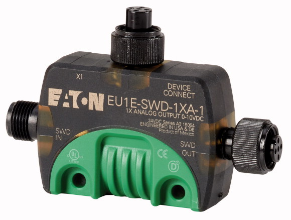
SmartWire-DT IP67 T-Connector analog module, one 0 - 10 V analog output with power supply, one M12 I/O socket
SmartWire-DT module with IP67 degree of protection, can be used to connect one analog output, 24 VDC 70 mA short-circuit proof sensor power supply, automatic address setting, 0 – 10 V output, 12-bit resolution, max. output current of 10 mA, short-circuit proof, I/O connection with M12 socket
| Product range | SmartWire-DT slave |
| Basic function | Analog modules |
| Function | For connection of analog I/O signals |
| Short Description | Output: 0 - 10 V |
| Analog | 1 |
| Connection to SmartWire-DT | yes |
| Standards | IEC/EN 61131-2 |
| Dimensions (W x H x D) | 85.6 x 56.9 x 20.1 mm |
| Weight | 0.07 kg |
| Mounting | DIN-rail, screw fixing (M4), mounting section (Clip M20) |
| Mounting position | As required |
| Power supply >Power loss [P] |
1.2 W |
| Climatic proofing | Dry heat to IEC 60068-2-2 Damp heat as per EN 60068-2-3 |
| Air pressure (operation) | 795 - 1080 hPa |
| Ambient temperature >Operation [ϑ] |
-25 - +70 °C |
| Ambient temperature >Storage / Transport [ϑ] |
-40 - +70 °C |
| Relative humidity >Condensation |
permissible |
| Relative humidity >Relative humidity, non-condensing (IEC/EN 60068-2-30) |
5 - 95 % |
| Protection type (IEC/EN 60529, EN50178, VBG 4) | IP69K |
| Vibrations (IEC/EN 61131-2:2008) >Constant amplitude 3,5 mm |
5 - 8.4 Hz |
| Vibrations (IEC/EN 61131-2:2008) >Constant acceleration 1 g |
8.4 - 150 Hz |
| Mechanical shock resistance (IEC/EN 60068-2-27) semi-sinusoidal 30 g/11 ms | 9 Impacts |
| Drop to IEC/EN 60068-2-31 [Drop height] | 50 mm |
| Free fall, packaged (IEC/EN 60068-2-32) | 0.3 m |
| Overvoltage category | II |
| Pollution degree | 3 |
| Electrostatic discharge (IEC/EN 61131-2:2008) >Air discharge (Level 3) |
8 kV |
| Electrostatic discharge (IEC/EN 61131-2:2008) >Contact discharge (Level 2) |
4 kV |
| Electromagnetic fields (IEC/EN 61131-2:2008) >80 - 1000 MHz |
10 V/m |
| Electromagnetic fields (IEC/EN 61131-2:2008) >1.4 - 2 GHz |
3 V/m |
| Electromagnetic fields (IEC/EN 61131-2:2008) >2 - 2.7 GHz |
1 V/m |
| Radio interference suppression (SmartWire-DT) | EN 55011 Class A |
| Burst (IEC/EN 61131-2:2008, Level 3) >Supply cable |
2 kV |
| Burst (IEC/EN 61131-2:2008, Level 3) >Signal lines |
1 kV |
| Burst (IEC/EN 61131-2:2008, Level 3) >SmartWire-DT cables |
1 kV |
| Surge (IEC/EN 61131-2:2008, Level 1) >Surge power cables |
0.5 kV |
| Surge (IEC/EN 61131-2:2008, Level 1) >Surge I/O cables |
1 kV |
| Radiated RFI (IEC/EN 61131-2:2008, Level 3) | 10 V |
| Station type | SmartWire-DT slave |
| Setting the baud rate | automatic |
| Baud rate (data transfer speed) | maximum2000 kbps |
| Status SmartWire-DT | Green LED |
| SWD-IN | M12 plug (A-keyed), 5 pole |
| SWD-OUT | M12 socket (A-keyed), 5 pole |
| Current consumption (24V, without sensor and without I/O supply) >Current consumption (24 V SWD supply) |
52 mA |
| Sensor supply >Max. current consumption per M12 I/O plug |
70 mA |
| Sensor supply >Overload and short-circuit proof |
yes, with diagnostics |
| Terminal for I/O sensor >Connection type |
5-pin M12 socket (A-keyed) |
| Quantity | 1 (2-wire connection, screened) |
| Parameter setting >Type |
Voltage |
| Voltage >Output voltage |
0 -10 V |
| Voltage >Max. output current |
10 mA |
| Overload and short-circuit proof | yes |
| Resolution | 12 Bit |
| Conversion time | 20 ms |
| Total error | ± 1 % |
| Repetition accuracy | ± 0.5 % |
| Outputs to SmartWire-DT | No |
| Rated operational current for specified heat dissipation [In] | 0 A |
| Heat dissipation per pole, current-dependent [Pvid] | 0 W |
| Equipment heat dissipation, current-dependent [Pvid] | 0 W |
| Static heat dissipation, non-current-dependent [Pvs] | 1.2 W |
| Heat dissipation capacity [Pdiss] | 0 W |
| Operating ambient temperature min. | -25 °C |
| Operating ambient temperature max. | +70 °C |
| Degree of Protection | IP69K |
| 10.2 Strength of materials and parts >10.2.2 Corrosion resistance |
Meets the product standard´s requirements. |
| 10.2 Strength of materials and parts >10.2.3.1 Verification of thermal stability of enclosures |
Meets the product standard´s requirements. |
| 10.2 Strength of materials and parts >10.2.3.2 Verification of resistance of insulating materials to normal heat |
Meets the product standard´s requirements. |
| 10.2 Strength of materials and parts >10.2.3.3 Verification of resistance of insulating materials to abnormal heat and fire due to internal electric effects |
Meets the product standard´s requirements. |
| 10.2 Strength of materials and parts >10.2.4 Resistance to ultra-violet (UV) radiation |
Meets the product standard´s requirements. |
| 10.2 Strength of materials and parts >10.2.5 Lifting |
Does not apply, since the entire switchgear needs to be evaluated. |
| 10.2 Strength of materials and parts >10.2.6 Mechanical impact |
Does not apply, since the entire switchgear needs to be evaluated. |
| 10.2 Strength of materials and parts >10.2.7 Inscriptions |
Meets the product standard´s requirements. |
| 10.3 Degree of protection of ASSEMBLIES | Meets the product standard´s requirements. |
| 10.4 Clearances and creepage distances | Meets the product standard´s requirements. |
| 10.5 Protection against electric shock | Does not apply, since the entire switchgear needs to be evaluated. |
| 10.6 Incorporation of switching devices and components | Does not apply, since the entire switchgear needs to be evaluated. |
| 10.7 Internal electrical circuits and connections | Is the panel builder´s responsibility. |
| 10.8 Connections for external conductors | Is the panel builder´s responsibility. |
| 10.9 Insulation properties >10.9.2 Power-frequency electric strength |
Is the panel builder´s responsibility. |
| 10.9 Insulation properties >10.9.3 Impulse withstand voltage |
Is the panel builder´s responsibility. |
| 10.9 Insulation properties >10.9.4 Testing of enclosures made of insulating material |
Is the panel builder´s responsibility. |
| 10.10 Temperature rise | The panel builder is responsible for the temperature rise calculation. Eaton will provide heat dissipation data for the devices. |
| 10.11 Short-circuit rating | Is the panel builder´s responsibility. |
| 10.12 Electromagnetic compatibility | Is the panel builder´s responsibility. |
| 10.13 Mechanical function | The device meets the requirements, provided the information in the instruction leaflet (IL) is observed. |
| Supply voltage AC 50 Hz | 0 - 0 V |
| Supply voltage AC 60 Hz | 0 - 0 V |
| Supply voltage DC | 0 - 0 V |
| Voltage type of supply voltage | DC |
| Input, current | No |
| Input, voltage | No |
| Input, resistor | No |
| Input, resistance thermometer | No |
| Input, thermocouple | No |
| Input signal, configurable | No |
| Resolution of the analogue inputs | 0 Bit |
| Output, current | No |
| Output, voltage | Yes |
| Output signal configurable | Yes |
| Resolution of the analogue outputs | 12 Bit |
| Number of analogue inputs | 0 |
| Number of analogue outputs | 1 |
| Analogue inputs configurable | No |
| Analogue outputs configurable | Yes |
| Number of HW-interfaces industrial Ethernet | 0 |
| Number of interfaces PROFINET | 0 |
| Number of HW-interfaces RS-232 | 0 |
| Number of HW-interfaces RS-422 | 0 |
| Number of HW-interfaces RS-485 | 0 |
| Number of HW-interfaces serial TTY | 0 |
| Number of HW-interfaces parallel | 0 |
| Number of HW-interfaces Wireless | 0 |
| Number of HW-interfaces USB | 0 |
| Number of HW-interfaces other | 0 |
| Supporting protocol for TCP/IP | No |
| Supporting protocol for PROFIBUS | No |
| Supporting protocol for CAN | No |
| Supporting protocol for INTERBUS | No |
| Supporting protocol for ASI | No |
| Supporting protocol for KNX | No |
| Supporting protocol for MODBUS | No |
| Supporting protocol for Data-Highway | No |
| Supporting protocol for DeviceNet | No |
| Supporting protocol for SUCONET | No |
| Supporting protocol for LON | No |
| Supporting protocol for PROFINET IO | No |
| Supporting protocol for PROFINET CBA | No |
| Supporting protocol for SERCOS | No |
| Supporting protocol for Foundation Fieldbus | No |
| Supporting protocol for EtherNet/IP | No |
| Supporting protocol for AS-Interface Safety at Work | No |
| Supporting protocol for DeviceNet Safety | No |
| Supporting protocol for INTERBUS-Safety | No |
| Supporting protocol for PROFIsafe | No |
| Supporting protocol for SafetyBUS p | No |
| Supporting protocol for other bus systems | Yes |
| Radio standard Bluetooth | No |
| Radio standard WLAN 802.11 | No |
| Radio standard GPRS | No |
| Radio standard GSM | No |
| Radio standard UMTS | No |
| IO link master | No |
| System accessory | Yes |
| Degree of protection (IP) | IP69K |
| Degree of protection (NEMA) | |
| Type of electric connection | Other |
| Fieldbus connection over separate bus coupler possible | Yes |
| Rail mounting possible | Yes |
| Wall mounting/direct mounting | Yes |
| Front build in possible | No |
| Rack-assembly possible | No |
| Suitable for safety functions | No |
| Category according to EN 954-1 | |
| SIL according to IEC 61508 | None |
| Performance level acc. EN ISO 13849-1 | None |
| Appendant operation agent (Ex ia) | No |
| Appendant operation agent (Ex ib) | No |
| Explosion safety category for gas | None |
| Explosion safety category for dust | None |
| Width | 85.6 mm |
| Height | 56.9 mm |
| Depth | 20.1 mm |
| UL File No. | E170645 |
| North America Certification | UL listed, CSA certified |
| Specially designed for North America | No |
Tüm hakları saklıdır. Mnelko Endüstriyel San. ve Tic.Ltd.Şti. 2024