SKU: Eaton-173026
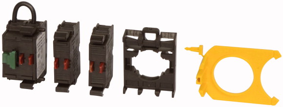
Combination of contact element and self-monitoring contact element M22-K01SMC10 with screw terminals, M22-A mounting adapter, and M22-XSMC signaling contact actuator., 1 N/O, 3 NC
Contact element, Connection technique: Screw terminals, Fixing: Front fixing, Description: Combination of contact element and self-monitoring contact element M22-K01SMC10 with screw terminals, M22-A mounting adapter, and M22-XSMC signaling contact actuator., The N/O in the self-monitoring contact element is actuated when mounted with M22-XSMC., Contacts N/O = Normally open: 1 N/O, Contacts N/C = Normally closed: 3 NC, Contacts Notes: = safety function, by positive opening to IEC/EN 60947-5-1, Degree of Protection: IP20, Connection to SmartWire-DT: no, Standards: IEC 60947-5-1
| Basic function accessories | Self-monitoring contact elements |
| Description | Combination of contact element and self-monitoring contact element M22-K01SMC10 with screw terminals, M22-A mounting adapter, and M22-XSMC signaling contact actuator. The N/O in the self-monitoring contact element is actuated when mounted with M22-XSMC. |
| Connection technique | Screw terminals |
| Fixing | Front fixing |
| Degree of Protection | IP20 |
| Connection to SmartWire-DT | no |
| Approval | |
| N/O = Normally open | |
| N/C = Normally closed | 1 N/O |
| Notes | 3 NC  |
| Contact sequence | = safety function, by positive opening to IEC/EN 60947-5-1 |
| Contact diagram | |
| Connection technique | |
| Standards | |
| Actuating force | Screw terminals |
| Operating torque (screw terminals) | |
| Degree of Protection | IEC 60947-5-1 |
| Climatic proofing | ≦ 15 n |
| Ambient temperature >Open |
≦ 0.8 Nm |
| Terminal capacities >Solid |
IP20 |
| Terminal capacities >Stranded |
Damp heat, constant, to IEC 60068-2-78 Damp heat, cyclic, to IEC 60068-2-30 |
| Terminal capacities >Flexible with ferrule |
-25 - +70 °C |
| Rated impulse withstand voltage [Uimp] | 0.75 - 2.5 mm2 |
| Rated insulation voltage [Ui ] | 0.5 - 2.5 mm2 |
| Overvoltage category/pollution degree | 0.5 - 1.5 mm2 |
| Max. short-circuit protective device >Fuseless |
|
| Max. short-circuit protective device >Fuse [gG/gL] |
6000 V AC |
| Rated operational current [Ie
] >AC-15 >115 V [Ie ] |
500 V |
| Rated operational current [Ie
] >AC-15 >220 V 230 V 240 V [Ie] |
III/3 |
| Rated operational current [Ie
] >AC-15 >380 V 400 V 415 V [Ie] |
PKZM0-10/FAZ-B6/1 Type |
| Rated operational current [Ie
] >AC-15 >500 V [Ie] |
10 A |
| Rated operational current [Ie
] >DC-13 >24 V [Ie ] |
|
| Rated operational current [Ie
] >DC-13 >42 V [Ie ] |
6 A |
| Rated operational current [Ie
] >DC-13 >60 V [Ie ] |
6 A |
| Rated operational current [Ie
] >DC-13 >110 V [Ie ] |
4 A |
| Rated operational current [Ie
] >DC-13 >220 V [Ie ] |
2 A |
| Rated operational current for specified heat dissipation [In] | 3 A |
| Heat dissipation per pole, current-dependent [Pvid] | 1.7 A |
| Equipment heat dissipation, current-dependent [Pvid] | 1.2 A |
| Static heat dissipation, non-current-dependent [Pvs] | 0.6 A |
| Heat dissipation capacity [Pdiss] | 0.3 A |
| Operating ambient temperature min. | |
| Operating ambient temperature max. | 6 A |
| 10.2 Strength of materials and parts >10.2.2 Corrosion resistance |
0.11 W |
| 10.2 Strength of materials and parts >10.2.3.1 Verification of thermal stability of enclosures |
0 W |
| 10.2 Strength of materials and parts >10.2.3.2 Verification of resistance of insulating materials to normal heat |
0 W |
| 10.2 Strength of materials and parts >10.2.3.3 Verification of resistance of insulating materials to abnormal heat and fire due to internal electric effects |
0 W |
| 10.2 Strength of materials and parts >10.2.4 Resistance to ultra-violet (UV) radiation |
-25 °C |
| 10.2 Strength of materials and parts >10.2.5 Lifting |
+70 °C |
| 10.2 Strength of materials and parts >10.2.6 Mechanical impact |
|
| 10.2 Strength of materials and parts >10.2.7 Inscriptions |
Meets the product standard´s requirements. |
| 10.3 Degree of protection of ASSEMBLIES | Meets the product standard´s requirements. |
| 10.4 Clearances and creepage distances | Meets the product standard´s requirements. |
| 10.5 Protection against electric shock | Meets the product standard´s requirements. |
| 10.6 Incorporation of switching devices and components | Meets the product standard´s requirements. |
| 10.7 Internal electrical circuits and connections | Does not apply, since the entire switchgear needs to be evaluated. |
| 10.8 Connections for external conductors | Does not apply, since the entire switchgear needs to be evaluated. |
| 10.9 Insulation properties >10.9.2 Power-frequency electric strength |
Meets the product standard´s requirements. |
| 10.9 Insulation properties >10.9.3 Impulse withstand voltage |
Does not apply, since the entire switchgear needs to be evaluated. |
| 10.9 Insulation properties >10.9.4 Testing of enclosures made of insulating material |
Meets the product standard´s requirements. |
| 10.10 Temperature rise | Does not apply, since the entire switchgear needs to be evaluated. |
| 10.11 Short-circuit rating | Does not apply, since the entire switchgear needs to be evaluated. |
| 10.12 Electromagnetic compatibility | Is the panel builder´s responsibility. |
| 10.13 Mechanical function | Is the panel builder´s responsibility. |
| Number of contacts as change-over contact | Is the panel builder´s responsibility. |
| Number of contacts as normally open contact | Is the panel builder´s responsibility. |
| Number of contacts as normally closed contact | Is the panel builder´s responsibility. |
| Number of fault-signal switches | The panel builder is responsible for the temperature rise calculation. Eaton will provide heat dissipation data for the devices. |
| Rated operation current Ie at AC-15, 230 V | Is the panel builder´s responsibility. The specifications for the switchgear must be observed. |
| Type of electric connection | Is the panel builder´s responsibility. The specifications for the switchgear must be observed. |
| Model | The device meets the requirements, provided the information in the instruction leaflet (IL) is observed. |
| Mounting method | |
| Lamp holder | |
| Product Standards | 0 |
| UL File No. | 0 |
| UL Category Control No. | 3 |
| CSA File No. | 0 |
| CSA Class No. | 6 A |
| North America Certification | Screw connection |
Tüm hakları saklıdır. Mnelko Endüstriyel San. ve Tic.Ltd.Şti. 2024