SKU: Eaton-170124
Gateway, SWD, 99 SWD cards on PROFINET
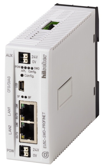
SmartWire-DT gateway for connection to the field bus and for supply of the SmartWire-DT card and switchgears. A connection to PROFINET can be established using the integrated 100 Mbit/s Ethernet switch and a slave configuration. Up to 99 SmartWire-DT modules can be connected. The gateway features a separate USB diagnostic interface.
| Product range | SmartWire-DT coordinators |
| Function | for connection to field bus PROFINET as PROFINET IO-Device |
| Short Description | Used to connect the SmartWire-DT communication system to industrial field bus systems. Powers SmartWire-DT modules and switchgear |
| Description | SmartWire-DT gateway for connecting up to 99 SmartWire-DT modules to an Industrial Ethernet network and for powering the SmartWire-DT modules and switchgear. A connection to PROFINET as a PROFINET I/O device can be established using the integrated 100 Mbit/s Ethernet switch and a slave configuration. The gateway features a separate USB diagnostic interface (mini USB). |
| Accessories | Connection of up to 99 SWD slaves |
| Standards | IEC/EN 61131-2 |
| Approvals >Approvals |
UL CSA |
| Dimensions (W x H x D) | 35 x 90 x 124 mm |
| Weight | 0.16 kg |
| Mounting | Top-hat rail IEC/EN 60715, 35 mm or screw fixing using fixing brackets ZB4-101-GF1 (accessories) |
| Mounting position | As required |
| Protection type (IEC/EN 60529, EN50178, VBG 4) | IP20 |
| Vibrations (IEC/EN 61131-2:2008) >Constant amplitude 3,5 mm |
5 - 9 Hz |
| Vibrations (IEC/EN 61131-2:2008) >Constant acceleration 1 g |
9 - 150 Hz |
| Mechanical shock resistance (IEC/EN 60068-2-27) semi-sinusoidal 15 g/11 ms | 9 Impacts |
| Drop to IEC/EN 60068-2-31 [Drop height] | 50 mm |
| Free fall, packaged (IEC/EN 60068-2-32) | 1 m |
| Overvoltage category | II |
| Pollution degree | 2 |
| Electrostatic discharge (IEC/EN 61131-2:2008) >Air discharge (Level 3) |
8 kV |
| Electrostatic discharge (IEC/EN 61131-2:2008) >Contact discharge (Level 2) |
4 kV |
| Electromagnetic fields (IEC/EN 61131-2:2008) >80 - 1000 MHz |
10 V/m |
| Electromagnetic fields (IEC/EN 61131-2:2008) >1.4 - 2 GHz |
3 V/m |
| Electromagnetic fields (IEC/EN 61131-2:2008) >2 - 2.7 GHz |
1 V/m |
| Radio interference suppression | EN 55011 Class A |
| Burst (IEC/EN 61131-2:2008, Level 3) >Supply cable |
2 kV |
| Burst (IEC/EN 61131-2:2008, Level 3) >Fieldbus cable |
1 kV |
| Burst (IEC/EN 61131-2:2008, Level 3) >SmartWire-DT cable |
1 kV |
| Surge (IEC/EN 61131-2:2008, Level 1) >Supply cable |
0.5 kV |
| Radiated RFI (IEC/EN 61131-2:2008, Level 3) | 10 V |
| Climatic environmental conditions >Climatic proofing |
In accordance with IEC 60068-2 |
| Climatic environmental conditions >Ambient temperature >Operation [ϑ] |
-25 - +55 °C |
| Climatic environmental conditions >Ambient temperature >Storage [ϑ] |
-40 - +70 °C |
| Atmospheric conditions
>Relative humidity, non-condensing (IEC/EN 60068-2-30) |
5 - 95 % |
| Atmospheric conditions
>Air pressure (operation) |
795 - 1080 hPa |
| Rated operational voltage [UAux] | 24 V DC (-15/+20%) V |
| Residual ripple on the input voltage | ≦ 5 % |
| Protection against polarity reversal | Yes |
| Max. current [Imax] | 3 A |
| Short-circuit rating | no, external fuse FAZ Z3 |
| Power loss [P] | Normally 1 W |
| Potential isolation | No |
| Rated operating voltage of 24-V-DC slaves | typ. UAux - 0.2 V |
| Supply voltage [UPow] | 24 V DC (-15/+20%) V |
| Input voltage ripple | ≦ 5 % |
| Siemens MPI, (optional) | yes |
| Rated current [I] | 0.7 A |
| Overload proof | yes |
| Inrush current and duration | 44 A/2 ms A |
| Heat dissipation at 24 V DC | 4.4 W |
| Potential isolation between UPow and 15 V SmartWire-DT supply voltage | No |
| Bridging voltage dips | 10 ms |
| Repetition rate | 1 s |
| Status indication | yes LED |
| Rated operating voltage [Ue] | 14,5 ± 3 % V |
| max. current [Imax] | 0.7 A |
| Short-circuit rating | Yes |
| Connection type | Push in terminals |
| Solid | 0.2 - 1.5 mm2 |
| Flexible with ferrule | 0.25 - 1.5 mm2 |
| UL/CSA solid or stranded | 24 - 16 AWG |
| Station type | SmartWire-DT master |
| Number of SmartWire-DT slaves | 99 |
| Baud Rates | 125 250 kBd |
| Status indication | SmartWire-DT master LED: red/green Configurations LED: red/green LED |
| Connections | Plug, 8-pole |
| Plug connectors | Blade terminal SWD4-8MF2 |
| Module type | PROFINET IO Device |
| Protocol | PROFINET |
| Input data, max. | 800 Byte |
| Output data, max. | 642 Byte |
| Baud Rate >Baud Rates |
100 MBit/s |
| Station address | IP |
| Address allocation | viaPROFINET |
| Status display interface [Multi colour] | APL, SF, BF, LINK, RX/TX LED |
| Connection design for field bus | 2 x RJ45 (2-channel switch) |
| Potential isolation | Yes |
| Other technical data (sheet catalogue) | Technical data |
| Notes | If contactors with a total current consumption > 3 A are connected, a power feeder module EU5C-SWD-PF1/2 has to be used. If SWD modules with a total current consumption > 0.7 A are connected, a power feeder module EU5C-SWD-PF2 has to be used. |
| Rated operational current for specified heat dissipation [In] | 0 A |
| Heat dissipation per pole, current-dependent [Pvid] | 0 W |
| Equipment heat dissipation, current-dependent [Pvid] | 0 W |
| Static heat dissipation, non-current-dependent [Pvs] | 1 W |
| Heat dissipation capacity [Pdiss] | 0 W |
| Operating ambient temperature min. | -25 °C |
| Operating ambient temperature max. | +55 °C |
| Degree of Protection | IP20 |
| 10.2 Strength of materials and parts >10.2.2 Corrosion resistance |
Meets the product standard´s requirements. |
| 10.2 Strength of materials and parts >10.2.3.1 Verification of thermal stability of enclosures |
Meets the product standard´s requirements. |
| 10.2 Strength of materials and parts >10.2.3.2 Verification of resistance of insulating materials to normal heat |
Meets the product standard´s requirements. |
| 10.2 Strength of materials and parts >10.2.3.3 Verification of resistance of insulating materials to abnormal heat and fire due to internal electric effects |
Meets the product standard´s requirements. |
| 10.2 Strength of materials and parts >10.2.4 Resistance to ultra-violet (UV) radiation |
Meets the product standard´s requirements. |
| 10.2 Strength of materials and parts >10.2.5 Lifting |
Does not apply, since the entire switchgear needs to be evaluated. |
| 10.2 Strength of materials and parts >10.2.6 Mechanical impact |
Does not apply, since the entire switchgear needs to be evaluated. |
| 10.2 Strength of materials and parts >10.2.7 Inscriptions |
Meets the product standard´s requirements. |
| 10.3 Degree of protection of ASSEMBLIES | Meets the product standard´s requirements. |
| 10.4 Clearances and creepage distances | Meets the product standard´s requirements. |
| 10.5 Protection against electric shock | Does not apply, since the entire switchgear needs to be evaluated. |
| 10.6 Incorporation of switching devices and components | Does not apply, since the entire switchgear needs to be evaluated. |
| 10.7 Internal electrical circuits and connections | Is the panel builder´s responsibility. |
| 10.8 Connections for external conductors | Is the panel builder´s responsibility. |
| 10.9 Insulation properties >10.9.2 Power-frequency electric strength |
Is the panel builder´s responsibility. |
| 10.9 Insulation properties >10.9.3 Impulse withstand voltage |
Is the panel builder´s responsibility. |
| 10.9 Insulation properties >10.9.4 Testing of enclosures made of insulating material |
Is the panel builder´s responsibility. |
| 10.10 Temperature rise | The panel builder is responsible for the temperature rise calculation. Eaton will provide heat dissipation data for the devices. |
| 10.11 Short-circuit rating | Is the panel builder´s responsibility. |
| 10.12 Electromagnetic compatibility | Is the panel builder´s responsibility. |
| 10.13 Mechanical function | The device meets the requirements, provided the information in the instruction leaflet (IL) is observed. |
| Supply voltage AC 50 Hz | 0 - 0 V |
| Supply voltage AC 60 Hz | 0 - 0 V |
| Supply voltage DC | 20.4 - 28.8 V |
| Voltage type of supply voltage | DC |
| Supporting protocol for TCP/IP | No |
| Supporting protocol for PROFIBUS | No |
| Supporting protocol for CAN | No |
| Supporting protocol for INTERBUS | No |
| Supporting protocol for ASI | No |
| Supporting protocol for KNX | No |
| Supporting protocol for MODBUS | No |
| Supporting protocol for Data-Highway | No |
| Supporting protocol for DeviceNet | No |
| Supporting protocol for SUCONET | No |
| Supporting protocol for LON | No |
| Supporting protocol for SERCOS | No |
| Supporting protocol for PROFINET IO | Yes |
| Supporting protocol for PROFINET CBA | No |
| Supporting protocol for Foundation Fieldbus | No |
| Supporting protocol for EtherNet/IP | No |
| Supporting protocol for AS-Interface Safety at Work | No |
| Supporting protocol for DeviceNet Safety | No |
| Supporting protocol for INTERBUS-Safety | No |
| Supporting protocol for PROFIsafe | No |
| Supporting protocol for SafetyBUS p | No |
| Supporting protocol for other bus systems | No |
| Radio standard Bluetooth | No |
| Radio standard WLAN 802.11 | No |
| Radio standard GPRS | No |
| Radio standard GSM | No |
| Radio standard UMTS | No |
| IO link master | No |
| System accessory | Yes |
| Degree of protection (IP) | IP20 |
| With potential separation | No |
| Fieldbus connection over separate bus coupler possible | No |
| Rail mounting possible | Yes |
| Wall mounting/direct mounting | Yes |
| Front build in possible | No |
| Rack-assembly possible | No |
| Suitable for safety functions | Yes |
| Category according to EN 954-1 | |
| SIL according to IEC 61508 | None |
| Performance level acc. EN ISO 13849-1 | None |
| Appendant operation agent (Ex ia) | No |
| Appendant operation agent (Ex ib) | No |
| Explosion safety category for gas | None |
| Explosion safety category for dust | None |
| Width | 35 mm |
| Height | 90 mm |
| Depth | 127 mm |
| UL File No. | E221530 |
| UL Category Control No. | NRQA |
| CSA File No. | UL report applies to both US and Canada |
| North America Certification | UL listed, CSA certified |
| Specially designed for North America | No |
| Current Limiting Circuit-Breaker | No |
Tüm hakları saklıdır. Mnelko Endüstriyel San. ve Tic.Ltd.Şti. 2024