SKU: Eaton-135530
Connection, SmartWireDarwin, for NZM
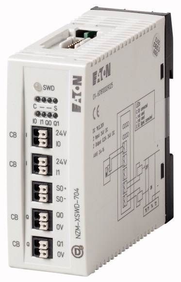
Optional accessories for the circuit-breaker series NZM offers a comprehensive portfolio of application options for use world wide. The mounting is always flexible and easy thanks to the modular function groups. Notes: the module implements the data connection between the NZM2/3/4 with electronic release and the SmartWire-DT. The switch can also be switched remote using a motor drive. Retentive memory for energy data (kWh). energy data is transmitted through digital input (S 0) from an external energy measuring module NZN...-XMC-SO. 2 digital inputs for the switch status. 2 transistor outputs for remote switching. Status data: NZM: ON/OFF/TRIPPED, load warnings, reason for last trip, actual current value, switch type actual settings of the rotary coding switches. A connection cable for the circuit-breaker and two NZM auxiliary contacts (1xNO, 1xNC) are included as standard.
| Product range | SmartWire-DT slave | ||||||||||||||||||||||||||||||||||||||||||
| Subrange | SmartWire-DT module NZM circuit-breakers | ||||||||||||||||||||||||||||||||||||||||||
| Product range | Accessories | ||||||||||||||||||||||||||||||||||||||||||
| Standard/Approval | IEC | ||||||||||||||||||||||||||||||||||||||||||
| Construction size | NZM2/3/4 | ||||||||||||||||||||||||||||||||||||||||||
| Accessories | Accessories, diagnostics & communication | ||||||||||||||||||||||||||||||||||||||||||
| Function | The module implements the data connection between the NZM2/3/4 with electronic release and SmartWire-DT. | ||||||||||||||||||||||||||||||||||||||||||
| Description | A switch with a remote operator can also be remotely operated with the module. Two digital inputs for the switch status 2 transistor outputs for remote switching Retentive memory for energy data (kWh) Energy data is transmitted through digital input (S0) from an external energy measuring module NZN...-XMC-SO. |
||||||||||||||||||||||||||||||||||||||||||
| Messages | Status data NZM: ON/OFF/TRIPPED Load warnings Reason for last trip Actual current value in A Switch type Actual settings of the rotary coding switches |
||||||||||||||||||||||||||||||||||||||||||
| Information about equipment supplied | A connection cable (1.90 m) for the circuit-breaker and two NZM auxiliary contacts (1 x NO, 1 x NC) are included as standard. | ||||||||||||||||||||||||||||||||||||||||||
| For use with | SmartWire-DT interface for NZM circuit-breakers | ||||||||||||||||||||||||||||||||||||||||||
| Connection to SmartWire-DT | yes | ||||||||||||||||||||||||||||||||||||||||||
| Standards | IEC/EN 61131-2 EN 50178 |
||||||||||||||||||||||||||||||||||||||||||
| Approvals >shipping classification |
DNV GL BV LRS |
||||||||||||||||||||||||||||||||||||||||||
| Dimensions (W x H x D) | 35 x 90 x 101 mm | ||||||||||||||||||||||||||||||||||||||||||
| Weight | 0.1 kg | ||||||||||||||||||||||||||||||||||||||||||
| Mounting | Top-hat rail IEC/EN 60715, 35 mm | ||||||||||||||||||||||||||||||||||||||||||
| Mounting position | Vertical | ||||||||||||||||||||||||||||||||||||||||||
| Relative humidity >Condensation |
Take appropriate measures to prevent condensation | ||||||||||||||||||||||||||||||||||||||||||
| Relative humidity >Relative humidity, non-condensing (IEC/EN 60068-2-30) |
5 - 95 % | ||||||||||||||||||||||||||||||||||||||||||
| Protection type (IEC/EN 60529, EN50178, VBG 4) | IP20 | ||||||||||||||||||||||||||||||||||||||||||
| Vibrations (IEC/EN 61131-2:2008) >Constant amplitude 3,5 mm |
5 - 8.4 Hz | ||||||||||||||||||||||||||||||||||||||||||
| Vibrations (IEC/EN 61131-2:2008) >Constant acceleration 1 g |
8.4 - 150 Hz | ||||||||||||||||||||||||||||||||||||||||||
| Mechanical shock resistance (IEC/EN 60068-2-27) semi-sinusoidal 15 g/11 ms | 9 Impacts | ||||||||||||||||||||||||||||||||||||||||||
| Drop to IEC/EN 60068-2-31 [Drop height] | 50 mm | ||||||||||||||||||||||||||||||||||||||||||
| Free fall, packaged (IEC/EN 60068-2-32) | 0.3 m | ||||||||||||||||||||||||||||||||||||||||||
| Overvoltage category | II | ||||||||||||||||||||||||||||||||||||||||||
| Pollution degree | 2 | ||||||||||||||||||||||||||||||||||||||||||
| Electrostatic discharge (IEC/EN 61131-2:2008) >Air discharge (Level 3) |
8 kV | ||||||||||||||||||||||||||||||||||||||||||
| Electrostatic discharge (IEC/EN 61131-2:2008) >Contact discharge (Level 2) |
4 kV | ||||||||||||||||||||||||||||||||||||||||||
| Electromagnetic fields (IEC/EN 61131-2:2008) >80 - 1000 MHz |
10 V/m | ||||||||||||||||||||||||||||||||||||||||||
| Electromagnetic fields (IEC/EN 61131-2:2008) >1.4 - 2 GHz |
3 V/m | ||||||||||||||||||||||||||||||||||||||||||
| Electromagnetic fields (IEC/EN 61131-2:2008) >2 - 2.7 GHz |
1 V/m | ||||||||||||||||||||||||||||||||||||||||||
| Radio interference suppression (SmartWire-DT) | EN 55011 Class A | ||||||||||||||||||||||||||||||||||||||||||
| Burst (IEC/EN 61131-2:2008, Level 3) >Supply cable |
2 kV | ||||||||||||||||||||||||||||||||||||||||||
| Burst (IEC/EN 61131-2:2008, Level 3) >Signal lines |
1 kV | ||||||||||||||||||||||||||||||||||||||||||
| Burst (IEC/EN 61131-2:2008, Level 3) >SmartWire-DT cables |
1 kV | ||||||||||||||||||||||||||||||||||||||||||
| Radiated RFI (IEC/EN 61131-2:2008, Level 3) | 10 V | ||||||||||||||||||||||||||||||||||||||||||
| Station type | SmartWire-DT slave | ||||||||||||||||||||||||||||||||||||||||||
| Setting the baud rate | automatic | ||||||||||||||||||||||||||||||||||||||||||
| Status SmartWire-DT | Green LED | ||||||||||||||||||||||||||||||||||||||||||
| Connection | Plug, 8-pole Connection plug: External device plug SWD4-8SF2-5 |
||||||||||||||||||||||||||||||||||||||||||
| Current consumption (15 V SWD supply) |
|
||||||||||||||||||||||||||||||||||||||||||
| Terminal for I/O sensor >Connection type |
Push in terminals | ||||||||||||||||||||||||||||||||||||||||||
| Terminal for I/O sensor >Solid |
0.2 - 1.5 (AWG 24 - 16) mm2 | ||||||||||||||||||||||||||||||||||||||||||
| Terminal for I/O sensor >Flexible with ferrule |
0.25 - 1.5 mm2 | ||||||||||||||||||||||||||||||||||||||||||
| Quantity | 8 | ||||||||||||||||||||||||||||||||||||||||||
| Input current | Normally 4 at 24 V DC mA | ||||||||||||||||||||||||||||||||||||||||||
| Limit value type 1 | Low < 5V DC;High > 15V DC | ||||||||||||||||||||||||||||||||||||||||||
| Input delay | High->Low < 0.2 ms Low -> High typ. < 0,2 ms |
||||||||||||||||||||||||||||||||||||||||||
| Status display inputs | yellow LED | ||||||||||||||||||||||||||||||||||||||||||
| Quantity | 4 | ||||||||||||||||||||||||||||||||||||||||||
| Output current | Normally 0.5 at 24 V DC A | ||||||||||||||||||||||||||||||||||||||||||
| Short-circuit tripping current | max. 1.2 over 3 ms A | ||||||||||||||||||||||||||||||||||||||||||
| Lamp load [RLL ] | ≦ ≤ 3 W | ||||||||||||||||||||||||||||||||||||||||||
| Overload proof | yes, with diagnostics | ||||||||||||||||||||||||||||||||||||||||||
| Switching capacity | EN 60947-5-1 utilization category DC-13 | ||||||||||||||||||||||||||||||||||||||||||
| Inputs for SmartWire-DT | Yes | ||||||||||||||||||||||||||||||||||||||||||
| Outputs to SmartWire-DT | Yes | ||||||||||||||||||||||||||||||||||||||||||
| Operating ambient temperature min. | -25 °C | ||||||||||||||||||||||||||||||||||||||||||
| Operating ambient temperature max. | +55 °C | ||||||||||||||||||||||||||||||||||||||||||
| 10.2 Strength of materials and parts >10.2.2 Corrosion resistance |
Meets the product standard´s requirements. | ||||||||||||||||||||||||||||||||||||||||||
| 10.2 Strength of materials and parts >10.2.3.1 Verification of thermal stability of enclosures |
Meets the product standard´s requirements. | ||||||||||||||||||||||||||||||||||||||||||
| 10.2 Strength of materials and parts >10.2.3.2 Verification of resistance of insulating materials to normal heat |
Meets the product standard´s requirements. | ||||||||||||||||||||||||||||||||||||||||||
| 10.2 Strength of materials and parts >10.2.3.3 Verification of resistance of insulating materials to abnormal heat and fire due to internal electric effects |
Meets the product standard´s requirements. | ||||||||||||||||||||||||||||||||||||||||||
| 10.2 Strength of materials and parts >10.2.4 Resistance to ultra-violet (UV) radiation |
Meets the product standard´s requirements. | ||||||||||||||||||||||||||||||||||||||||||
| 10.2 Strength of materials and parts >10.2.5 Lifting |
Does not apply, since the entire switchgear needs to be evaluated. | ||||||||||||||||||||||||||||||||||||||||||
| 10.2 Strength of materials and parts >10.2.6 Mechanical impact |
Does not apply, since the entire switchgear needs to be evaluated. | ||||||||||||||||||||||||||||||||||||||||||
| 10.2 Strength of materials and parts >10.2.7 Inscriptions |
Meets the product standard´s requirements. | ||||||||||||||||||||||||||||||||||||||||||
| 10.3 Degree of protection of ASSEMBLIES | Does not apply, since the entire switchgear needs to be evaluated. | ||||||||||||||||||||||||||||||||||||||||||
| 10.4 Clearances and creepage distances | Meets the product standard´s requirements. | ||||||||||||||||||||||||||||||||||||||||||
| 10.5 Protection against electric shock | Does not apply, since the entire switchgear needs to be evaluated. | ||||||||||||||||||||||||||||||||||||||||||
| 10.6 Incorporation of switching devices and components | Does not apply, since the entire switchgear needs to be evaluated. | ||||||||||||||||||||||||||||||||||||||||||
| 10.7 Internal electrical circuits and connections | Is the panel builder´s responsibility. | ||||||||||||||||||||||||||||||||||||||||||
| 10.8 Connections for external conductors | Is the panel builder´s responsibility. | ||||||||||||||||||||||||||||||||||||||||||
| 10.9 Insulation properties >10.9.2 Power-frequency electric strength |
Is the panel builder´s responsibility. | ||||||||||||||||||||||||||||||||||||||||||
| 10.9 Insulation properties >10.9.3 Impulse withstand voltage |
Is the panel builder´s responsibility. | ||||||||||||||||||||||||||||||||||||||||||
| 10.9 Insulation properties >10.9.4 Testing of enclosures made of insulating material |
Is the panel builder´s responsibility. | ||||||||||||||||||||||||||||||||||||||||||
| 10.10 Temperature rise | The panel builder is responsible for the temperature rise calculation. Eaton will provide heat dissipation data for the devices. | ||||||||||||||||||||||||||||||||||||||||||
| 10.11 Short-circuit rating | Is the panel builder´s responsibility. The specifications for the switchgear must be observed. | ||||||||||||||||||||||||||||||||||||||||||
| 10.12 Electromagnetic compatibility | Is the panel builder´s responsibility. The specifications for the switchgear must be observed. | ||||||||||||||||||||||||||||||||||||||||||
| 10.13 Mechanical function | The device meets the requirements, provided the information in the instruction leaflet (IL) is observed. | ||||||||||||||||||||||||||||||||||||||||||
| Supply voltage AC 50 Hz | 0 - 0 V | ||||||||||||||||||||||||||||||||||||||||||
| Supply voltage AC 60 Hz | 0 - 0 V | ||||||||||||||||||||||||||||||||||||||||||
| Supply voltage DC | 24 - 24 V | ||||||||||||||||||||||||||||||||||||||||||
| Voltage type of supply voltage | DC | ||||||||||||||||||||||||||||||||||||||||||
| Supporting protocol for TCP/IP | No | ||||||||||||||||||||||||||||||||||||||||||
| Supporting protocol for PROFIBUS | No | ||||||||||||||||||||||||||||||||||||||||||
| Supporting protocol for CAN | No | ||||||||||||||||||||||||||||||||||||||||||
| Supporting protocol for INTERBUS | No | ||||||||||||||||||||||||||||||||||||||||||
| Supporting protocol for ASI | No | ||||||||||||||||||||||||||||||||||||||||||
| Supporting protocol for KNX | No | ||||||||||||||||||||||||||||||||||||||||||
| Supporting protocol for MODBUS | No | ||||||||||||||||||||||||||||||||||||||||||
| Supporting protocol for Data-Highway | No | ||||||||||||||||||||||||||||||||||||||||||
| Supporting protocol for DeviceNet | No | ||||||||||||||||||||||||||||||||||||||||||
| Supporting protocol for SUCONET | No | ||||||||||||||||||||||||||||||||||||||||||
| Supporting protocol for LON | No | ||||||||||||||||||||||||||||||||||||||||||
| Supporting protocol for SERCOS | No | ||||||||||||||||||||||||||||||||||||||||||
| Supporting protocol for PROFINET IO | No | ||||||||||||||||||||||||||||||||||||||||||
| Supporting protocol for PROFINET CBA | No | ||||||||||||||||||||||||||||||||||||||||||
| Supporting protocol for Foundation Fieldbus | No | ||||||||||||||||||||||||||||||||||||||||||
| Supporting protocol for EtherNet/IP | No | ||||||||||||||||||||||||||||||||||||||||||
| Supporting protocol for AS-Interface Safety at Work | No | ||||||||||||||||||||||||||||||||||||||||||
| Supporting protocol for DeviceNet Safety | No | ||||||||||||||||||||||||||||||||||||||||||
| Supporting protocol for INTERBUS-Safety | No | ||||||||||||||||||||||||||||||||||||||||||
| Supporting protocol for PROFIsafe | No | ||||||||||||||||||||||||||||||||||||||||||
| Supporting protocol for SafetyBUS p | No | ||||||||||||||||||||||||||||||||||||||||||
| Supporting protocol for other bus systems | Yes | ||||||||||||||||||||||||||||||||||||||||||
| Radio standard Bluetooth | No | ||||||||||||||||||||||||||||||||||||||||||
| Radio standard WLAN 802.11 | No | ||||||||||||||||||||||||||||||||||||||||||
| Radio standard GPRS | No | ||||||||||||||||||||||||||||||||||||||||||
| Radio standard GSM | No | ||||||||||||||||||||||||||||||||||||||||||
| Radio standard UMTS | No | ||||||||||||||||||||||||||||||||||||||||||
| IO link master | No | ||||||||||||||||||||||||||||||||||||||||||
| System accessory | Yes | ||||||||||||||||||||||||||||||||||||||||||
| Degree of protection (IP) | IP20 | ||||||||||||||||||||||||||||||||||||||||||
| With potential separation | Yes | ||||||||||||||||||||||||||||||||||||||||||
| Fieldbus connection over separate bus coupler possible | Yes | ||||||||||||||||||||||||||||||||||||||||||
| Rail mounting possible | Yes | ||||||||||||||||||||||||||||||||||||||||||
| Wall mounting/direct mounting | Yes | ||||||||||||||||||||||||||||||||||||||||||
| Front build in possible | No | ||||||||||||||||||||||||||||||||||||||||||
| Rack-assembly possible | No | ||||||||||||||||||||||||||||||||||||||||||
| Suitable for safety functions | No | ||||||||||||||||||||||||||||||||||||||||||
| Category according to EN 954-1 | B | ||||||||||||||||||||||||||||||||||||||||||
| SIL according to IEC 61508 | None | ||||||||||||||||||||||||||||||||||||||||||
| Performance level acc. EN ISO 13849-1 | None | ||||||||||||||||||||||||||||||||||||||||||
| Appendant operation agent (Ex ia) | No | ||||||||||||||||||||||||||||||||||||||||||
| Appendant operation agent (Ex ib) | No | ||||||||||||||||||||||||||||||||||||||||||
| Explosion safety category for gas | None | ||||||||||||||||||||||||||||||||||||||||||
| Explosion safety category for dust | None | ||||||||||||||||||||||||||||||||||||||||||
| Width | 35 mm | ||||||||||||||||||||||||||||||||||||||||||
| Height | 102 mm | ||||||||||||||||||||||||||||||||||||||||||
| Depth | 90 mm | ||||||||||||||||||||||||||||||||||||||||||
| North America Certification | Request filed for UL and CSA |
Tüm hakları saklıdır. Mnelko Endüstriyel San. ve Tic.Ltd.Şti. 2024