SKU: Eaton-125402
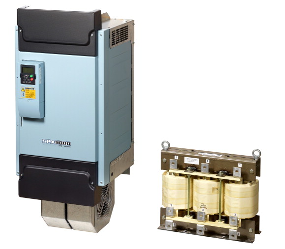
Variable frequency drive, 400 V AC, 3-phase, 160 kW, IP00, OLED display, FR10
Variable frequency drive, Part group reference (e.g. DIL): SPX, Rated operational voltage: Ue = 400 V AC, 3-phase, 480 V AC, 3-phase, 500 V AC, 3-phase, Output voltage with Ve: U2 = 400 V AC, 3-phase, 480 V AC, 3-phase, 500 V AC, 3-phase, Mains voltage (50/60Hz): ULN = 380 (-15%) - 500 (+10%) V, Rated operational current At 150% overload: Ie = 300 A, Rated operational current At 110% overload: Ie = 385 A, Note: Overload cycle for 60 s every 600 s, Assigned motor rating Note: For AC motors with internal and external ventilation with 50 Hz / 60 Hz, Overload cycle for 60 s every 600 s, at 400 V, 50 Hz, Assigned motor rating 150 % Overload: P = 160 kW, 110 % Overload: P = 200 kW, 150 % Overload: IM = 279 A, 110 % Overload: IM = 349 A, Assigned motor rating Note: at 440 - 480 V, 60 Hz, Assigned motor rating 150 % Overload: P = 250 HP, 110 % Overload: P = 300 HP, Assigned motor rating 150 % Overload: IM = 302 A, 110 % Overload: IM = 361 A, Degree of Protection: IP00, Fieldbus connection (optional): PROFIBUS-DP, LonWorks, CANopen®, DeviceNet, Modbus-TCP, BACnet/IP, Fitted with: OLED display, Frame size: FR10, Standards: Specification for general requirements: IEC/EN 61800-2, EMC requirements: IEC/EN 61800-3, Safety requirements: IEC/EN 61800-5-1
| Product range | Variable frequency drives |
| Part group reference (e.g. DIL) | SPX |
| Rated operational voltage [Ue] | 400 V AC, 3-phase 480 V AC, 3-phase 500 V AC, 3-phase |
| Output voltage with Ve [U2] | 400 V AC, 3-phase 480 V AC, 3-phase 500 V AC, 3-phase |
| Mains voltage (50/60Hz) [ULN] | 380 (-15%) - 500 (+10%) V |
| At 150% overload [Ie] | |
| At 110% overload [Ie] | 300 A |
| Note | 385 A |
| Note | |
| Note | For AC motors with internal and external ventilation with 50 Hz / 60 Hz |
| 150 % Overload [P] | Overload cycle for 60 s every 600 s |
| 110 % Overload [P] | at 400 V, 50 Hz |
| 150 % Overload [IM] | 160 kW |
| 110 % Overload [IM] | 200 kW |
| Note | 279 A |
| 150 % Overload [P] | 349 A |
| 110 % Overload [P] | at 440 - 480 V, 60 Hz |
| 150 % Overload [IM] | 250 HP |
| 110 % Overload [IM] | 300 HP |
| Degree of Protection | 302 A |
| Fieldbus connection (optional) | 361 A |
| Fitted with | IP00 |
| Frame size | PROFIBUS-DP PROFINET EtherCAT EtherNet/IP LonWorks CANopen® DeviceNet Modbus-TCP Modbus-RTU BACnet MS/TP |
| Connection to SmartWire-DT | OLED display |
| Standards | FR10 |
| Certifications | no |
| Approvals | |
| Production quality | Specification for general requirements: IEC/EN 61800-2 EMC requirements: IEC/EN 61800-3 Safety requirements: IEC/EN 61800-5-1 |
| Climatic proofing [ρw] | CE, UL, cUL, RCM |
| Ambient temperature >Operating ambient temperature min. |
DNV |
| Ambient temperature >Operating ambient temperature max. |
RoHS, ISO 9001 |
| Ambient temperature >Storage [ϑ] |
< 95% relative humidity, no condensation, no corrosion, no dripping water % |
| Radio interference level >Radio interference class (EMC) |
-10 °C |
| Radio interference level >Environment (EMC) |
+40 °C |
| Mounting position | -40 - +70 °C |
| Altitude | C2, C3, depending on the motor cable length, the connected load, and ambient conditions. External radio interference suppression filters (optional) may be necessary. |
| Degree of Protection | 1st and 2nd environments as per EN 61800-3 |
| Protection against direct contact | Vertical |
| Supply >Rated operational voltage [Ue] |
0 - 1000 m above sea level above 1000 m with 1 % performance reduction per 100 m max. 3000 m m |
| Supply >Mains voltage (50/60Hz) [ULN] |
IP00 |
| Supply >System configuration |
BGV A3 (VBG4, finger- and back-of-hand proof) |
| Supply >Supply frequency [fLN] |
|
| Supply >Frequency range [fLN] |
400 V AC, 3-phase 480 V AC, 3-phase 500 V AC, 3-phase |
| Power section >Function |
380 (-15%) - 500 (+10%) V |
| Power section >Output voltage with Ve [U2] |
AC supply systems with earthed center point |
| Power section >Output Frequency [f2] |
50/60 Hz |
| Power section >Switching frequency [fPWM] |
45–66 (± 0%) Hz |
| Power section >Operation Mode |
Variable frequency drive with internal DC link and IGBT inverter |
| Power section >Frequency resolution (setpoint value) [Δf] |
400 V AC, 3-phase 480 V AC, 3-phase 500 V AC, 3-phase |
| Power section >Rated operational current >At 150% overload [Ie] |
0 - 50/60 (max. 320) Hz |
| Power section >Rated operational current >At 110% overload [Ie] |
3.6 adjustable 1 - 6 kHz |
| Power section >Fitted with |
U/f control sensorless vector control (SLV) optional: Vector control with feedback (CLV) |
| Power section >Frame size |
0.01 Hz |
| Motor feeder >Note |
300 A |
| Motor feeder >Note |
385 A |
| Motor feeder >Note |
OLED display |
| Motor feeder >150 % Overload [P] |
FR10 |
| Motor feeder >110 % Overload [P] |
For AC motors with internal and external ventilation with 50 Hz / 60 Hz |
| Motor feeder >Note |
Overload cycle for 60 s every 600 s |
| Motor feeder >150 % Overload [P] |
at 400 V, 50 Hz |
| Motor feeder >110 % Overload [P] |
160 kW |
| External control voltage [Uc] | 200 kW |
| Reference voltage [Us] | at 440 - 480 V, 60 Hz |
| Analog inputs | 250 HP |
| Analog outputs | 300 HP |
| Digital inputs | |
| Digital outputs | 24 V DC (max. 250 mA) V |
| Relay outputs | 10 V DC (max. 10 mA) V |
| Motor feeder >motor choke >150 % overload (CT/IH, at 50 °C) |
2, parameterizable, 0 - 10 V DC, 0/4 - 20 mA |
| Motor feeder >motor choke >110 % overload (VT/IL, at 40 °C) |
1, parameterizable, 0/4 - 20 mA |
| Motor feeder >Sine filter >110 % overload (VT/IL, at 40 °C) |
6, parameterizable, max. 30 V DC |
| Rated operational current for specified heat dissipation [In] | 1, parameterizable, 48 V DC/50 mA |
| Heat dissipation per pole, current-dependent [Pvid] | 2, parameterizable, N/O, 8 A (24 V DC) / 8 A (250 V AC) / 0,4 A (125 V DC) |
| Equipment heat dissipation, current-dependent [Pvid] | |
| Static heat dissipation, non-current-dependent [Pvs] | DX-LM3-303 |
| Heat dissipation capacity [Pdiss] | DX-LM3-450 |
| Operating ambient temperature min. | DX-SIN3-440 |
| Operating ambient temperature max. | |
| 10.2 Strength of materials and parts >10.2.2 Corrosion resistance |
300 A |
| 10.2 Strength of materials and parts >10.2.3.1 Verification of thermal stability of enclosures |
0 W |
| 10.2 Strength of materials and parts >10.2.3.2 Verification of resistance of insulating materials to normal heat |
4000 W |
| 10.2 Strength of materials and parts >10.2.3.3 Verification of resistance of insulating materials to abnormal heat and fire due to internal electric effects |
0 W |
| 10.2 Strength of materials and parts >10.2.4 Resistance to ultra-violet (UV) radiation |
0 W |
| 10.2 Strength of materials and parts >10.2.5 Lifting |
-10 °C |
| 10.2 Strength of materials and parts >10.2.6 Mechanical impact |
+40 °C |
| 10.2 Strength of materials and parts >10.2.7 Inscriptions |
|
| 10.3 Degree of protection of ASSEMBLIES | Meets the product standard´s requirements. |
| 10.4 Clearances and creepage distances | Meets the product standard´s requirements. |
| 10.5 Protection against electric shock | Meets the product standard´s requirements. |
| 10.6 Incorporation of switching devices and components | Meets the product standard´s requirements. |
| 10.7 Internal electrical circuits and connections | Meets the product standard´s requirements. |
| 10.8 Connections for external conductors | Does not apply, since the entire switchgear needs to be evaluated. |
| 10.9 Insulation properties >10.9.2 Power-frequency electric strength |
Does not apply, since the entire switchgear needs to be evaluated. |
| 10.9 Insulation properties >10.9.3 Impulse withstand voltage |
Meets the product standard´s requirements. |
| 10.9 Insulation properties >10.9.4 Testing of enclosures made of insulating material |
Does not apply, since the entire switchgear needs to be evaluated. |
| 10.10 Temperature rise | Meets the product standard´s requirements. |
| 10.11 Short-circuit rating | Does not apply, since the entire switchgear needs to be evaluated. |
| 10.12 Electromagnetic compatibility | Does not apply, since the entire switchgear needs to be evaluated. |
| 10.13 Mechanical function | Is the panel builder´s responsibility. |
| Mains voltage | Is the panel builder´s responsibility. |
| Mains frequency | Is the panel builder´s responsibility. |
| Number of phases input | Is the panel builder´s responsibility. |
| Number of phases output | Is the panel builder´s responsibility. |
| Max. output frequency | The panel builder is responsible for the temperature rise calculation. Eaton will provide heat dissipation data for the devices. |
| Max. output voltage | Is the panel builder´s responsibility. The specifications for the switchgear must be observed. |
| Nominal output current I2N | Is the panel builder´s responsibility. The specifications for the switchgear must be observed. |
| Max. output at quadratic load at rated output voltage | The device meets the requirements, provided the information in the instruction leaflet (IL) is observed. |
| Max. output at linear load at rated output voltage | |
| Relative symmetric net frequency tolerance | |
| Relative symmetric net voltage tolerance | 323 - 550 V |
| Number of analogue outputs | 50/60 Hz |
| Number of analogue inputs | 3 |
| Number of digital outputs | 3 |
| Number of digital inputs | 320 Hz |
| With control unit | 500 V |
| Application in industrial area permitted | 385 A |
| Application in domestic- and commercial area permitted | 200 kW |
| Supporting protocol for TCP/IP | 160 kW |
| Supporting protocol for PROFIBUS | 10 % |
| Supporting protocol for CAN | 10 % |
| Supporting protocol for INTERBUS | 1 |
| Supporting protocol for ASI | 2 |
| Supporting protocol for KNX | 1 |
| Supporting protocol for MODBUS | 6 |
| Supporting protocol for Data-Highway | Yes |
| Supporting protocol for DeviceNet | Yes |
| Supporting protocol for SUCONET | Yes |
| Supporting protocol for LON | Yes |
| Supporting protocol for PROFINET IO | Yes |
| Supporting protocol for PROFINET CBA | Yes |
| Supporting protocol for SERCOS | No |
| Supporting protocol for Foundation Fieldbus | No |
| Supporting protocol for EtherNet/IP | No |
| Supporting protocol for AS-Interface Safety at Work | Yes |
| Supporting protocol for DeviceNet Safety | Yes |
| Supporting protocol for INTERBUS-Safety | Yes |
| Supporting protocol for PROFIsafe | No |
| Supporting protocol for SafetyBUS p | Yes |
| Supporting protocol for BACnet | Yes |
| Supporting protocol for other bus systems | No |
| Number of HW-interfaces industrial Ethernet | No |
| Number of interfaces PROFINET | No |
| Number of HW-interfaces RS-232 | Yes |
| Number of HW-interfaces RS-422 | No |
| Number of HW-interfaces RS-485 | No |
| Number of HW-interfaces serial TTY | No |
| Number of HW-interfaces USB | No |
| Number of HW-interfaces parallel | No |
| Number of HW-interfaces other | No |
| With optical interface | Yes |
| With PC connection | 0 |
| Integrated breaking resistance | 0 |
| 4-quadrant operation possible | 1 |
| Type of converter | 0 |
| Degree of protection (IP) | 0 |
| Degree of protection (NEMA) | 0 |
| Height | 0 |
| Width | 0 |
| Depth | 0 |
| Product Standards | No |
| UL File No. | Yes |
| UL Category Control No. | No |
| CSA File No. | Yes |
| CSA Class No. | U converter |
| North America Certification | IP00 |
| Specially designed for North America | Other |
| Suitable for | 1165 mm |
| Max. Voltage Rating | 500 mm |
| Degree of Protection | 506 mm |
Tüm hakları saklıdır. Mnelko Endüstriyel San. ve Tic.Ltd.Şti. 2024