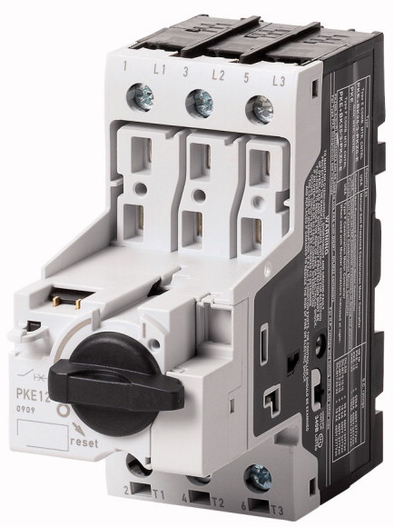
SKU: Eaton-121721
Circuit-breaker, Basic device with standard knob, 12 A, Without overload releases, Screw terminals
Basic device motor-protective circuit-breaker, isolating function, can be expanded without tools with PKE-XTU... electronic control units for motor protection. Expandable with auxiliary contacts, voltage release, current limiter, door coupling handles. world-market device
| Product range | PKE motor protective circuit-breakers with electronic wide-range overload protection up to 32 A |
| Basic function | Motor protection Motor protection for heavy starting duty |
| Single unit/Complete unit | Basic device with standard knob |
| Notes | |
| Connection technique | Also suitable for motors with efficiency class IE3. IE3-ready devices are identified by the logo on their packaging. |
| Setting range of useable overload releases [Ir] | Screw terminals |
| Function | 0.3 - 12 CSA |
| Rated uninterrupted current = rated operational current [Iu = Ie ] | Without overload releases |
| Standards | 12 A |
| Climatic proofing | |
| Ambient temperature >Storage |
IEC/EN 60947, VDE 0660,UL, CSA |
| Ambient temperature >Open |
Damp heat, constant, to IEC 60068-2-78 Damp heat, cyclic, to IEC 60068-2-30 |
| Ambient temperature >Enclosed |
- 40 - 80 °C |
| Mounting position | -25 - +55 °C |
| Direction of incoming supply | - 25 - 40 °C |
| Degree of protection >Device |
|
| Degree of protection >Terminations |
as required |
| Protection against direct contact when actuated from front (EN 50274) | IP20 |
| Mechanical shock resistance half-sinusoidal shock 10 ms to IEC 60068-2-27 | IP00 |
| Altitude | Finger and back-of-hand proof |
| Terminal capacity main cable >Screw terminals >Solid |
25 g |
| Terminal capacity main cable >Screw terminals >Flexible with ferrule to DIN 46228 |
Max. 2000 m |
| Terminal capacity main cable >Screw terminals >Solid or stranded |
1 x (1 - 6) 2 x (1 - 6) mm2 |
| Terminal capacity main cable >Screw terminals >Stripping length |
1 x (1 - 6) 2 x (1 - 6) mm2 |
| Specified tightening torque for terminal screws >Main cable |
14 - 10 AWG |
| Specified tightening torque for terminal screws >Control circuit cables |
10 mm |
| Rated impulse withstand voltage [Uimp] | 1.7 Nm |
| Overvoltage category/pollution degree | 1 Nm |
| Rated operational voltage [Ue ] | |
| Rated uninterrupted current = rated operational current [Iu = Ie ] | 6000 V AC |
| Rated frequency [f] | III/3 |
| Current heat loss (3 pole at operating temperature) | 690 V AC |
| Lifespan, mechanical [Operations] | 12 A |
| Lifespan, electrical (AC-3 at 400 V) >Lifespan, electrical [Operations] |
40 - 60 Hz |
| Max. operating frequency | 2.7 W |
| Motor switching capacity >AC-3 (up to 690V) |
0.05 x 10⁶ |
| Temperature compensation >to IEC/EN 60947, VDE 0660 |
0.05 x 10⁶ |
| Temperature compensation >Operating range |
60 Ops/h |
| Setting range of overload releases | 12 A |
| short-circuit release | |
| Short-circuit release tolerance | - 5…40 °C |
| Phase-failure sensitivity | - 25…55 °C |
| Rated operational current for specified heat dissipation [In] | 0.25 - 1 x Iu |
| Heat dissipation per pole, current-dependent [Pvid] | Basic device, fixed: 15.5 x Iu |
| Equipment heat dissipation, current-dependent [Pvid] | ± 20% |
| Static heat dissipation, non-current-dependent [Pvs] | IEC/EN 60947-4-1, VDE 0660 Part 102 |
| Heat dissipation capacity [Pdiss] | |
| Operating ambient temperature min. | 12 A |
| Operating ambient temperature max. | 0.9 W |
| 10.2 Strength of materials and parts >10.2.2 Corrosion resistance |
2.7 W |
| 10.2 Strength of materials and parts >10.2.3.1 Verification of thermal stability of enclosures |
0 W |
| 10.2 Strength of materials and parts >10.2.3.2 Verification of resistance of insulating materials to normal heat |
0 W |
| 10.2 Strength of materials and parts >10.2.3.3 Verification of resistance of insulating materials to abnormal heat and fire due to internal electric effects |
-25 °C |
| 10.2 Strength of materials and parts >10.2.4 Resistance to ultra-violet (UV) radiation |
+55 °C |
| 10.2 Strength of materials and parts >10.2.5 Lifting |
|
| 10.2 Strength of materials and parts >10.2.6 Mechanical impact |
Meets the product standard´s requirements. |
| 10.2 Strength of materials and parts >10.2.7 Inscriptions |
Meets the product standard´s requirements. |
| 10.3 Degree of protection of ASSEMBLIES | Meets the product standard´s requirements. |
| 10.4 Clearances and creepage distances | Meets the product standard´s requirements. |
| 10.5 Protection against electric shock | Meets the product standard´s requirements. |
| 10.6 Incorporation of switching devices and components | Does not apply, since the entire switchgear needs to be evaluated. |
| 10.7 Internal electrical circuits and connections | Does not apply, since the entire switchgear needs to be evaluated. |
| 10.8 Connections for external conductors | Meets the product standard´s requirements. |
| 10.9 Insulation properties >10.9.2 Power-frequency electric strength |
Does not apply, since the entire switchgear needs to be evaluated. |
| 10.9 Insulation properties >10.9.3 Impulse withstand voltage |
Meets the product standard´s requirements. |
| 10.9 Insulation properties >10.9.4 Testing of enclosures made of insulating material |
Does not apply, since the entire switchgear needs to be evaluated. |
| 10.10 Temperature rise | Does not apply, since the entire switchgear needs to be evaluated. |
| 10.11 Short-circuit rating | Is the panel builder´s responsibility. |
| 10.12 Electromagnetic compatibility | Is the panel builder´s responsibility. |
| 10.13 Mechanical function | Is the panel builder´s responsibility. |
| Overload release current setting | Is the panel builder´s responsibility. |
| Adjustment range undelayed short-circuit release | Is the panel builder´s responsibility. |
| With thermal protection | The panel builder is responsible for the temperature rise calculation. Eaton will provide heat dissipation data for the devices. |
| Phase failure sensitive | Is the panel builder´s responsibility. The specifications for the switchgear must be observed. |
| Switch off technique | Is the panel builder´s responsibility. The specifications for the switchgear must be observed. |
| Rated operating voltage | The device meets the requirements, provided the information in the instruction leaflet (IL) is observed. |
| Rated permanent current Iu | |
| Rated operation power at AC-3, 230 V | |
| Rated operation power at AC-3, 400 V | 0 - 0 A |
| Type of electrical connection of main circuit | 0 - 0 A |
| Type of control element | No |
| Device construction | No |
| With integrated auxiliary switch | Electronic |
| With integrated under voltage release | 690 - 690 V |
| Number of poles | 12 A |
| Rated short-circuit breaking capacity lcu at 400 V, AC | 0 kW |
| Degree of protection (IP) | 0 kW |
| Height | Screw connection |
| Width | Turn button |
| Depth | Built-in device fixed built-in technique |
| Product Standards | No |
| UL File No. | No |
| UL Category Control No. | 3 |
| CSA File No. | 0 kA |
| CSA Class No. | IP20 |
| North America Certification | 102.5 mm |
| Specially designed for North America | 45 mm |
| Characteristic curve | 102.5 mm |
| Characteristic curve | IEC/EN 60947-4-1; UL 60947-4-1; CSA - C22.2 No. 60947-4-1-14; CE marking |
| Characteristic curve | E36332 |
Tüm hakları saklıdır. Mnelko Endüstriyel San. ve Tic.Ltd.Şti. 2024