SKU: Eaton-121380
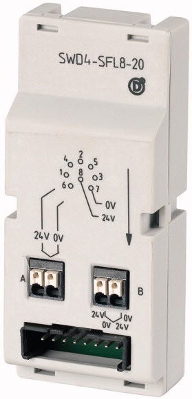
Switch cabinet bushing, SmartWire-DT, flat to round cable, socket
SmartWire-DT switch cabinet bushing, transition from SWD ribbon cable to round cable, double conductor run pluggable, additional control voltage feeder is possible for the motor starter and contactor, suitable for wall thicknesses up to 4mm, degree of protection IP67, drilling dimensions 18.5mm, connection of SWD ribbon cable with blade terminal SWD4-8MF2 8 pole, connection round cable via socket
| Basic function accessories | switch cabinet bushing |
| Product range | SmartWire-DT accessories |
| Degree of Protection | IP20 |
| For use with | M22-SWD… |
| Standards | IEC/EN 61131-2 EN 50178 |
| Dimensions (W x H x D) | 35 x 83 x 40 mm |
| Weight | 0.05 kg |
| Mounting position | As required |
| Power loss [P] | 1 W |
| Protection type (IEC/EN 60529, EN50178, VBG 4) | IP20 |
| Vibrations (IEC/EN 61131-2:2008) >Constant amplitude 3,5 mm >constant amplitude 0.15 mm max. |
8.4 Hz |
| Vibrations (IEC/EN 61131-2:2008) >Constant amplitude 3,5 mm >Constant amplitude 0.15 mm min. (RefExtrakt) |
5 Hz |
| Vibrations (IEC/EN 61131-2:2008) >Constant acceleration 1 g >constant acceleration 1 g max. |
150 Hz |
| Vibrations (IEC/EN 61131-2:2008) >Constant acceleration 1 g >constant acceleration 1 g min. |
8.4 Hz |
| Mechanical shock resistance (IEC/EN 60068-2-27) semi-sinusoidal 15 g/11 ms | 9 Impacts |
| Free fall, packaged (IEC/EN 60068-2-32) | 0.3 m |
| Electrostatic discharge (IEC/EN 61131-2:2008) >Air discharge (Level 3) |
8 kV |
| Electrostatic discharge (IEC/EN 61131-2:2008) >Contact discharge (Level 2) |
4 kV |
| Electromagnetic fields (IEC/EN 61131-2:2008) >2 - 2.7 GHz |
1 V/m |
| Electromagnetic fields (IEC/EN 61131-2:2008) >1.4 - 2 GHz |
3 V/m |
| Electromagnetic fields (IEC/EN 61131-2:2008) >80 - 1000 MHz |
10 V/m |
| Radiated RFI (IEC/EN 61131-2:2008, Level 3) | 10 V |
| Climatic proofing | Dry heat to IEC 60068-2-2 Damp heat as per EN 60068-2-3 |
| Air pressure (operation) | 795 - 1080 hPa |
| Ambient temperature >Operation [ϑ] |
-25 - +70 °C |
| Ambient temperature >Storage / Transport [ϑ] |
-40 - +70 °C |
| Ambient temperature >Relative humidity >Condensation |
Take appropriate measures to prevent condensation |
| Ambient temperature >Relative humidity >Relative humidity, non-condensing (IEC/EN 60068-2-30) |
5 - 95 % |
| Connection 1 | Plug, 8-pole |
| Number of insertion cycles | ≥ 200 |
| Connection 2 | M20 socket, 8 pole |
| Number of insertion cycles | ≥ 500 |
| Rated operational current for specified heat dissipation [In] | 0 A |
| Heat dissipation per pole, current-dependent [Pvid] | 0 W |
| Equipment heat dissipation, current-dependent [Pvid] | 0 W |
| Static heat dissipation, non-current-dependent [Pvs] | 1 W |
| Heat dissipation capacity [Pdiss] | 0 W |
| Operating ambient temperature min. | -25 °C |
| Operating ambient temperature max. | +70 °C |
| Degree of Protection | IP20 |
| 10.2 Strength of materials and parts >10.2.2 Corrosion resistance |
Meets the product standard´s requirements. |
| 10.2 Strength of materials and parts >10.2.3.1 Verification of thermal stability of enclosures |
Meets the product standard´s requirements. |
| 10.2 Strength of materials and parts >10.2.3.2 Verification of resistance of insulating materials to normal heat |
Meets the product standard´s requirements. |
| 10.2 Strength of materials and parts >10.2.3.3 Verification of resistance of insulating materials to abnormal heat and fire due to internal electric effects |
Meets the product standard´s requirements. |
| 10.2 Strength of materials and parts >10.2.4 Resistance to ultra-violet (UV) radiation |
Meets the product standard´s requirements. |
| 10.2 Strength of materials and parts >10.2.5 Lifting |
Does not apply, since the entire switchgear needs to be evaluated. |
| 10.2 Strength of materials and parts >10.2.6 Mechanical impact |
Does not apply, since the entire switchgear needs to be evaluated. |
| 10.2 Strength of materials and parts >10.2.7 Inscriptions |
Meets the product standard´s requirements. |
| 10.3 Degree of protection of ASSEMBLIES | Meets the product standard´s requirements. |
| 10.4 Clearances and creepage distances | Meets the product standard´s requirements. |
| 10.5 Protection against electric shock | Does not apply, since the entire switchgear needs to be evaluated. |
| 10.6 Incorporation of switching devices and components | Does not apply, since the entire switchgear needs to be evaluated. |
| 10.7 Internal electrical circuits and connections | Is the panel builder´s responsibility. |
| 10.8 Connections for external conductors | Is the panel builder´s responsibility. |
| 10.9 Insulation properties >10.9.2 Power-frequency electric strength |
Is the panel builder´s responsibility. |
| 10.9 Insulation properties >10.9.3 Impulse withstand voltage |
Is the panel builder´s responsibility. |
| 10.9 Insulation properties >10.9.4 Testing of enclosures made of insulating material |
Is the panel builder´s responsibility. |
| 10.10 Temperature rise | The panel builder is responsible for the temperature rise calculation. Eaton will provide heat dissipation data for the devices. |
| 10.11 Short-circuit rating | Is the panel builder´s responsibility. |
| 10.12 Electromagnetic compatibility | Is the panel builder´s responsibility. |
| 10.13 Mechanical function | The device meets the requirements, provided the information in the instruction leaflet (IL) is observed. |
| Type of electrical accessory | Plug |
| Type of mechanical accessory | Other |
| UL File No. | E29184 |
| UL Category Control No. | NKCR |
| CSA File No. | 2324643 |
| CSA Class No. | 3211-07 |
| North America Certification | UL listed, CSA certified |
| Specially designed for North America | No |
Tüm hakları saklıdır. Mnelko Endüstriyel San. ve Tic.Ltd.Şti. 2024